tProbe™ - T1 E1 VF and Serial Data Analysis and Emulation Hardware
This hardware incorporates all the features of the previous analyzer such as portability, USB interface, remote accessibility, scripting, and a vast collection of optional applications.
Request a Demo / Quote Brochure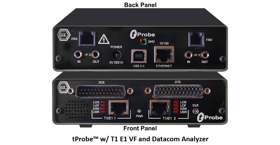
Overview
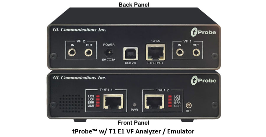
GL's tProbe™ is an enhanced version of our popular USB based T1 E1 VF Analyzer / Emulator. This hardware incorporates all the features of the previous analyzer such as portability, USB interface, remote accessibility, scripting, and a vast collection of optional applications.
GL's tProbe™ also includes ability to add optional boards such as the Datacom Analyzer, and FXO-FXS Simulation boards. The FXO port on tProbe™ allows to simulate a two-wire FXO device such as a telephone or a fax machine. This feature allows you to capture and analyze data from a two-wire telephone line, as well as to generate and transmit analog data onto that two-wire line.
Similarly, the FXS port on tProbe™ emulates a two-wire FXS service such as a telephone wall jack. This feature allows you to interface with an FXO device such as a telephone. Server commands allow you to provide standard FXS features such as monitoring for the off-hook line, sending ring signals, and providing dial tone.
GL's tProbe™ Datacom Analyzer is designed for the service installation, verification, and maintenance of Datacom and telecom equipments. It provides a software selectable interface to emulate DTE, DCE and monitor the Datacom lines for both synchronous (sync), and asynchronous (async) modes of operation.
GL offers two versions of the tProbe™ T1 E1 Datacom Analyzer:
- The first version is designed for domestic use and operates with AC mains power
- The second version, CE approved, is powered by USB 3.0
GL's Windows Client/Server software allows the user of T1 E1 analysis/emulation cards (with portable, dual, quad, and octal interfaces), the capability of remote operation, automation, and multi-device connectivity. Supported client is Python. Client can run under any operating system, including UNIX, LINUX, Windows, etc.
GL's Windows Client Python Module (WCPM) offers a client interface for the WCS. It enables a Python program to connect to one or more WCS, execute commands and receive responses. The Python client can connect to multiple WCS, controlling tProbe™ devices across various locations via TCP/IP. This capability facilitates task automation through scripts, repetitive testing at scheduled intervals, and flexible data export and saving.
GL's Protocol Analyzers offer comprehensive, non-intrusive monitoring by tapping the network under test across various communication links, including T1 E1 lines. With support for TDM, Wireless, Optical, and Packet networks, the analyzers help users easily identify improper protocol sequences, troubleshoot network infrastructure, user endpoints, and client applications. The intuitive software framework simplifies filtering frames that cause protocol violations, ensuring precise and efficient analysis. GL also provides the necessary tapping equipment to facilitate seamless network monitoring.
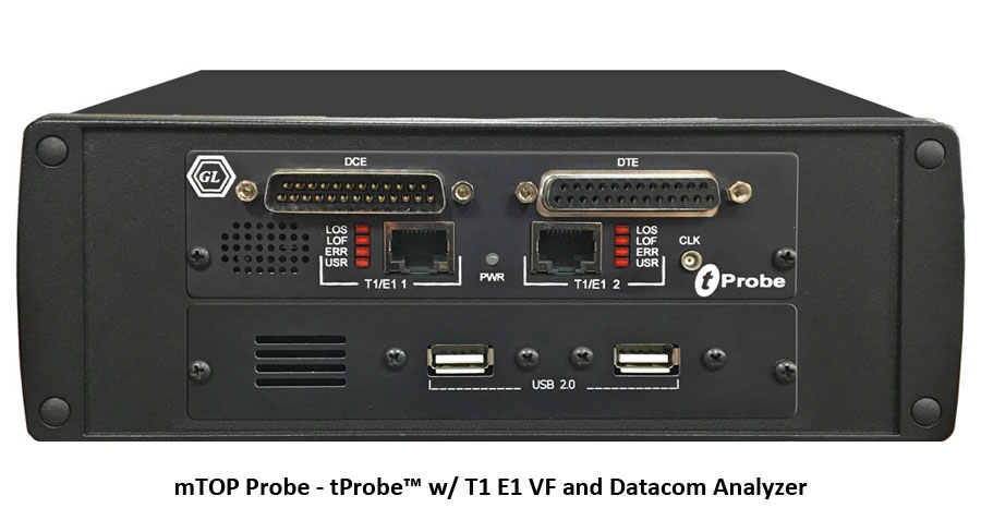
Probe T1 E1 Datacom Tester unit includes GL's USB based tProbe™ hardware unit with Datacom interfaces to test and verify the data communications equipment and circuits - specifically serial interfaces that provide clock, data, and control signals. Software selectable modes are provided to emulate DTE, DCE and non-intrusive monitoring for both synchronous (sync), and asynchronous (async) modes.
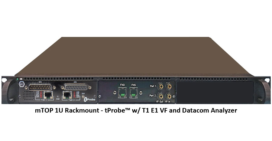
T1 E1 Datacom FXO FXS 1U rack-mount enclosure is a sleek appliance housing GL’s USB based tProbe™ with T1 E1 interfaces, FXO FXS card and Datacom card hardware units for unified testing experience of TDM and Analog technologies.
Increased Performance with 64-bit Support
GL’s T1 E1 analyzers supports both 32-bit and 64-bit applications. 64-bit support improves the performance of Protocol Analysers viz., ISDN, ISUP, GSM and allow users to monitor Hundreds to Thousands of Signaling Links simultaneously and continuously. Also, provides improved processing and response time for Statistics, Call Data Records, Search and other such functions.
Enhanced CCA application allows better processing and response time for multiple instances of CCA applications for long run tests. Similarly, all basic Intrusive and Non Intrusive applications such as BERT, Monitoring Applications, Oscilloscope, Spectral Display etc provide better processing and response time for multiple instances of monitoring and simulations windows.
MAPS™ Protocol Emulators are enhanced to provide improved performance for load generation and simulation of Protocols on 16 T1 E1 ports simultaneously.
Client Server commands support Thousands of Tasks simultaneously with number of successful thread creation. This helps to run Tx Rx File, Tx and Rx Tone and Tx Rx Digits on 24/31 Timeslots * 8 Ports * n (where n is the number of tProbe™ T1 E1 Cards)
Features
Recently tProbe™ was introduced with the following important enhancements:
- T1 E1 Pulse Shape, Jitter Measurement Analysis and Jitter Generation
- tProbe™ FXO and FXS board allows simulating FXO and FXS ports; FXO port to simulate a two-wire FXO device such as a telephone or a fax machine and the FXS port on tProbe™ to emulate a 2-wire FXS service such as a telephone wall jack.
- tProbe™ Datacom Analyzer board supports V.24, V.35, V.36, RS-449, RS-485, EIA-530 and EIA-530A interfaces and can be configured as DTE or DCE to test Channel Service Unit (CSU) and Data Service Unit (DSU) entities
- Software selectable T1 or E1 interface along with Drop and Insert
- Monitor the T1 E1 line conditions such as frame errors, violations, alarms, frequency, power level, and clock (or frame/bit) slips
- Protocol emulation including ISDN, CAS and SS7
- Python scripting support on both Windows® and Linux operating® systems
- TDM, ISDN, SS7 – High Density Voice
- VoIP, Frame Relay, Multilink Frame Relay, PPP and Multilink PPP, HDLC
- Physical layer analysis includes ability to send alarms and errors via SNMP Traps
- Routing and Bridging emulation over Multi T1 E1 WAN interfaces using MLPPP (Multi Link PPP) and MFR (Multi Link Frame relay) protocols
- Call Recording, Generation, and Monitoring for hundreds to thousands of calls in one platform
- Capable of simulating as well as decoding and demodulating fax calls over T1 E1 lines using Fax Simulator andFaxScan™
- Windows® and Linux Drivers for Open Source Applications
- Supports both 32-bit and 64-bit Windows® operating system.
- "Cross-port Through" and "Cross-port Transmit" Modes – these configurations make cabling with Drop/Insert and Fail-Safe Inline Monitoring very easy
- Support for all "basic applications" and "special applications"
- Comprehensive Analysis / Emulation of Voice, Data, Fax, Protocol, Analog, and Digital signals, including Echo and Voice Quality testing
- Improved circuitry for very accurate Digital Line Level measurements
- Ethernet Interface for future standalone operation
- Easy calibration
- Forward thinking hardware design for future daughter board expansion applications
- Lightweight (1.24 lbs) and small footprint (6.05" x 5.55" x 1.60 ")
- Switchable Line Level or Microphone input using 3.5 mm or Bantam physical connectors
- Enhanced VF Drop and VF Insert Capabilities using 3.5mm Balanced (Stereo), or Unbalanced (Mono) physical connections.
- Includes individual speakers (one speaker per card).
- The VF Tx and Rx impedance for tProbe™ analyzer supports software selectable 135, 150, 600, or 900 Ohm terminations. Additionally, the VF Rx impedance supports New High Impedance Monitor Termination (>50K Ohms), and external Microphone and Headset (Mic/HS) impedance .
- VF Tx Gains for tProbe™ analyzer ranges from -12 dB to +59.5 dB in 0.5 dB steps, and VF Rx Gains for tProbe™analyzer ranges from -63.5 dB to +9 dB in 0.5 dB steps.
GL's offers other popular forms of T1 E1 analysis hardware such as
- Octal/Quad T1 E1 Analyzer Boards - 8/4 port PCIe based cards for higher scalability and performance
- Dual Express T1 E1 Boards – 2 port PCIe based cards for compatibility with newer motherboards
- tScan16 - a high-density T1 E1 board with 16 ports and the newer PCIe (x1) bus interface.
Capabilities for future applications include -
- 10/100 Ethernet Interface for standalone embedded applications
- Standalone Embedded Processor Flash and Platform Flash (SDRAM 512 MByte)
- Additional Daughter Boards planned include ADSL, Octal T1 E1, T1 E1 Switch, and many more.
Portable Test Solution for TDM, SDH, Packet, and Analog
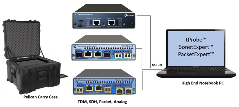
Solution 1 : tProbe™ + SonetExpert™ + PacketExpert™
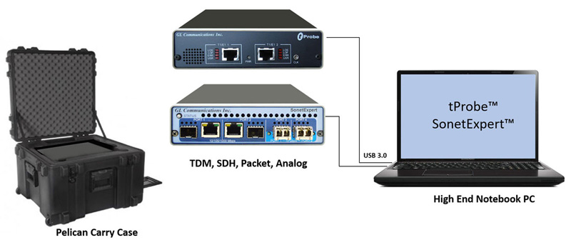
Solution 2 : tProbe™ + SonetExpert™
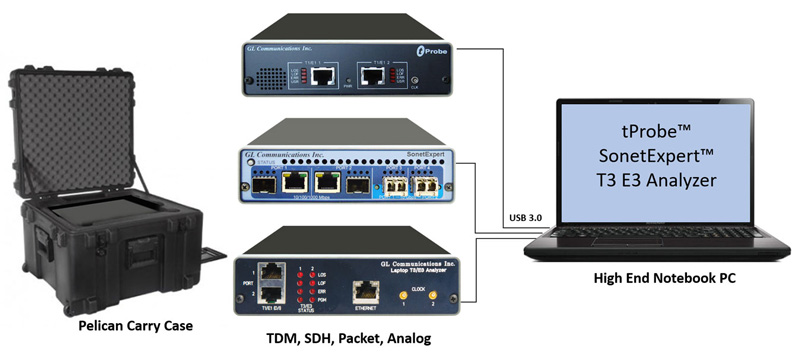
Solution 3 : tProbe™ + SonetExpert™ + T3 E3 Analyzer
Specifications
| Physical Interface | |
|---|---|
USB Connector |
(1) USB TYPE B Jack |
Ethernet Connector |
(1) 2.5 GigE Ethernet Port |
T1 E1 Connectors |
(2) RJ-48c Jacks |
Audio Connectors |
(4) 3.5 mm Balanced (Stereo) or unbalanced (Mono) Audio Jacks (TX & RX) |
External Clock Connector |
(1) MCX Coaxial Jack |
External Power Connector |
(1) Coaxial DC Power Jack (mates with 5.5mm x 2.1mm coaxial plug) |
| Physical Dimensions | |
|---|---|
Dimensions |
6.05 inches (153.67mm) (L) |
Weight |
1.24 lbs. (0.56 kg) |
Operating Temperature |
Temperature |
Altitude |
10,000 Feet |
Acoustic Noise |
NA |
| External Power Requirements | |
|---|---|
Power Adapter Requirements |
+5V @ 2A Max Power to the Center Ring |
| Optional Boards | |
|---|---|
2-Wire Daughter Board (One FXO, One FXS) |
FXO - RJ-11 |
Datacom Daughter Board |
Dual DB25 Connectors Support: |
| T1 E1 Line Interface | |
|---|---|
Framing Formats |
Unframed, D4 (T1) , ESF(T1), CAS(E1), FAS(E1), CRC4 |
Line Code format |
AMI, B8ZS (T1) or HDB3 (E1) |
Internal Clock Specification |
Standard: ± 3ppm Optional: ± 1ppm |
Output Clock Source |
Internal (± 1 ppm or 3 ppm), Recovered, External Clock |
T1 Output Level |
T1: 3.0V Base to Peak Selectable 0-655Ft Pulse Equalization Setting; Tx Capability - DSX-1 Outputs (to 655 feet) |
E1 Output Level |
E1: 3.0V ± 0.3V Base to Peak |
Input Level |
75 mV to 6V base to peak or -30 dBsx to -6 dBsx |
Line Built Out Selections |
0dB, -7.5dB, -15dB, -22.5dB for T1 only |
Loopback |
Normal (Outward and Inward) |
| Transmit | |
|---|---|
T1 E1 Interface Hardware Compliance |
- ANSI: T1.403.1995, T1.231-1993, T1.408 |
BERT Pattern Generation |
Pseudorandom patterns: (63) 26-1, (511) 29-1,
(2047) 211-1, (32767) 215-1, (1048575) 220-1, (8388607) 223-1,
QRSS. |
Alarm Insertion |
Blue, Yellow, Remote, Distant Multiframe |
Error Insertion |
BPV, Bit Error, Frame Error, CRC Errors, Burst Frames, Fixed Error Rate, Random Error Rate, auto logic from 10-2 to 10-9 for selectable 56K or 64Kps channels. |
Drop and Insert |
Any contiguous set of digital timeslots and/or audio input |
Facility Data Link |
T1 ESF Mode: Transmit/Receive Messages, Bit-Oriented Messages, and Files. |
Zero Suppression |
B7 Stuffing, Transparent, & B8ZS (T1) |
Signaling |
Robbed-Bit or Clear Channel |
Frequency Offset |
T1: +/- 615Hz E1: +/- 615Hz |
| Receive | |
|---|---|
Input Impedance |
100 ohms for Terminate and Monitor (T1) |
Terminations |
Terminate, Monitor, Bridge |
T1 Input Frequency |
1.544MHz ± 20KHz |
E1 Input Frequency |
2.048Mhz ± 20KHz |
Frequency Measurement |
± 1ppm |
Error Detection |
Frame Error, CRC Error, BPV Error, Logic Error, Frame Alignment Error |
Alarm Detection |
T1 - D4 Yellow Alarm, ESF Yellow Alarm |
Intrinsic Jitter |
Meets Jitter Tolerance: |
Input Range |
T1: Terminate, 0 to 36dB (Long Haul), DSX Monitor, Bridge |
| Display and Logging | |
|---|---|
BERT |
Bit Errors, Bit Error Rate, Error Seconds, Error Free Seconds, %EFS, Severely Error Seconds, % SES, Degraded Minutes, %Dmin, Loss Pattern Sync Count, Loss of Sync Seconds, Available Seconds, %Available Seconds, Unavailable Seconds, Bipolar Violations, BPV Rate, BPV Seconds, BPV Free Seconds, Frame Errors, FE Rate, FE Seconds, FE Free Seconds, with Detailed logging into disk file. |
Alarms |
Resync In Progress, Loss of Signal, Blue Alarm, Change of Frame Alignment, Bipolar Violation, Frame Error, Carrier Loss, Yellow Alarm, Out of Frame Events Counter, Error Super frame Counter, Bipolar Violations, Remote Alarm, Distant Multiframe Alarm, Signaling All Ones, CAS Multiframe Error, CRC4 Error. |
| VF Drop and Insert | |
|---|---|
| Refer to VF Drop and Insert Capabilities webpage for more details. | |
Rx Termination |
High Impedance (>50K Ohms) for Non-Intrusive Testing |
Tx Termination |
135, 150, 600, 900 Ohms |
Sampling Rates |
8KHz |
Datawidth (bits) |
Supports 8, 16, 20, 24, 32 Bit Data |
VF Tx Gains |
Supports -12 dB to +59 dB in 0.5dB Steps Gain (0.1 dB steps can also be accommodated in tProbe™) |
VF Rx Gains |
Supports -63.5 dB to +9 dB in 0.5dB Steps Attenuation (0.1 dB steps can also be accommodated in tProbe™) |
Connectors |
(4) 3.5 mm Balanced (Stereo) or Unbalanced (Mono) Audio Jacks (TX & RX) |
* Specifications subject to change without notice.
Device Certification:
Device is RoHS compliant and the tests were conducted by an independent laboratory.
Council Directive:
- EMC 2014/30/EU
- LVD 2014/35/EU
Safety Standards:
- EN61326-1: Ed. 2.0 (2012-07) {EN 61326-1: 2013}: Electrical equipment for measurement, control and laboratory use – EMC requirements – Part 1: General requirements
- CISPR 11:2015, Limits and methods of measurement of electromagnetic disturbance characteristics of industrial, scientific and medical (ISM) radio-frequency equipment, Amendment 1:2016
- IEC 61000-3-2:2014, Electromagnetic compatibility (EMC) – Part 3-2: Limits – Limits for harmonic current emissions (equipment input current ≤ 16A per phase)
- IEC 61000-3-3:2013, Electromagnetic compatibility (EMC) – Part 3-3: Limits – Limitation of voltage changes, voltage fluctuations and flicker in public low-voltage supply systems, for equipment with rated current ≤ 16 A per phase and not subject to conditional connection
- IEC 61000-4-2:2008, Electromagnetic compatibility (EMC) – Part 4-2: Testing and measurement techniques – Electrostatic discharge immunity test
- IEC 61000-4-3:2006, Electromagnetic compatibility (EMC) – Part 4-3: Testing and measurement techniques – Radiated, radiofrequency, electromagnetic field immunity test, Amendment 1:2007, Amendment 2:2010
- IEC 61000-4-4:2004, Electromagnetic compatibility (EMC) – Part 4-4: Testing and measurement
- IEC 61000-4-5:2006, Electromagnetic compatibility (EMC) – Part 4-5: Testing and measurement techniques – Surge immunity test
- IEC 61000-4-6:2008, Electromagnetic compatibility (EMC) – Part 4-6: Testing and measurement techniques – Immunity to conducted disturbances, induced by radio-frequency fields
- IEC 61000-4-11:2004, Electromagnetic compatibility (EMC) – Part 4-11: Testing and measurement techniques – Voltage dips, short interruptions, and voltage variations immunity tests
- IEC 61010-1:2010 CE Marking -LVD
Product Technical Comparison
| Feature | Requirement | T1 E1 Datacom Rack-mount |
|---|---|---|
| Portability | Portable or Fixed location | Rack-mount |
| Physical Connection | No of EIA-530 ports | 2 |
| Port Configuration | I/O interface | V.35, EIA_530, RS232, EIA_530A, RS449/RS-442 and X21 |
| DCE/DTE | DTE/DCE | |
| Manual RTS and DTR | Compliant | |
| Data inversion | Compliant | |
| Line termination | Compliant | |
| System Configuration | Full duplex Half duplex Self loop |
Full Duplex – Compliant Half Duplex – Device supports Monitor and Bridge mode Self Loop – Compliant |
| Data Rates | Async: 50 to 20k | Async: 75 bps to 115.2 Kbps and user configurable frequency |
| Sync: 50 to 10M | Sync: 300 bps to 16.384 Mbps and user configurable frequency | |
| Test Path | End-to-End | Compliant |
| Loopback | Compliant | |
| Monitoring | Compliant | |
| Test Patterns | Fixed patterns: MARK SPACE 1:1 1:7 1:16 2:8 3:24 |
Supported Patterns : All Ones, All Zeros, 1:1, 1:7, 3 in 24, CSU Loop-Up (00001), CSU Loop-Down (001), NIU Loop-Up (11000), NIU Loop-Down (11100) and User Defined Pattern (3 bits to 32 bits) |
| Pseudo random patterns: 63 (26-1) 511 (29-1) 2047 (211-1) 32,767 (215-1) 1,048,575 (220-1) 8,388,607 (223-1) QRSS |
Supported Patterns : 26-1, 29-1, 211-1, 215-1, 220-1, 223-1 and QRSS |
|
| Error Insertion | Manual | Compliant |
| Automated | Single : Single at time intervals (1 sec resolution) 10-2 to 10-9 bit error rate | |
| Messages | User message: Up to 1024 bits | Compliant |
| Binary/ASCII | Compliant | |
| Test Interval | Continuous and 10 to 100M bits | Ability to test continuously with the BERT application and BERT timed test with WCS |
| Line Data Encoding | Line encoding: FM0 FM1 Manchester Differential Manchester |
|
| Timing | Jitter measurement | Not Compliant |
| External clock | Compliant | |
| Internal clock accuracy: +5ppm | +/- 1 ppm Internal Clock | |
| Internal clock drift +5ppm/yr | +/- 1 ppm Internal Clock | |
| Data clock: Synchronous Recovered |
Compliant | |
| Round Trip Delay (RTD) | RTD: 1 microsecond or better |
Micro Second Precision |
| User Interface | Display | Windows based software application |
| Displays: RTS CTS DTR DSR LOS |
Supported | |
| External Links | Ethernet | Supported |
| USB | Supported | |
| Wireless | Not Supported | |
| Internal Battery | N/A | Not Compliant |
| Environmental Impact | RoHS REACH |
RoHS Compliant |
| Operating Environment | Temperature: 0oC to 35oC |
0° C to 50° C |
| Humidity: 20% to 90% |
10% - 95% Humidity, Non-condensing | |
| EMC/EMI: EN55032 EN55035 |
EMC 2014/30/EU LVD 2014/35/EU |
|
| Safety: AS/NZS 60950-1 AS/NZS 62368-1 |
IEC 61010-1:2010 CE Marking -LVD |
|
| Operating voltage: 230VAC nom. |
Operates on USB 2.0 and External Power supply 5V.2A |
Loopback
Universal T1 E1 Cards supports Normal (no cross-port), Cross-port Through, and Cross-port Transmit loopbacks.
Cross-port Through Loopback
This mode is similar to the standard Outward Loopback except that the signal received on Card 1 (Port 1) is transmitted out onto Card 2 (Port 2). Likewise the signal received on Card 2 (Port 2) is transmitted out onto Card 1 (Port 1). This feature allows monitoring T1 E1 lines in-line while still being protected from loss of power to the board. This mode is effected entirely thru relays and eliminates complex cabling.
Cross-port Transmit Mode Loopback
In this mode, the data that would normally be transmitted on Card 1 (Port 1) is diverted and transmitted on Card 2 (Port 2) and the data that would normally be transmitted on Card 2 (Port 2) is diverted and transmitted on Card 1 (Port 1). The receive paths are completely unaffected. This mode is particularly useful for Drop and Insert and Error Injection applications in which the board analyzes and may insert traffic running between two pieces of T1 E1 equipment. This feature also eliminates complex cabling.
Resources
Note: PCs which include GL hardware/software require Intel or AMD processors for compliance.
Please Note: The XX in the Item No. refers to the hardware platform, listed at the bottom of the Buyer's Guide, which the software will be running on. Therefore, XX can either be ETA or EEA (Octal/Quad Boards), PTA or PEA (tProbe Units), XUT or XUE (Dual PCIe Express) depending upon the hardware.
| Quick Links | |
| T1 E1 tProbe™ Brochure | |
| Frequency Calibration Procedure User Guide | |
|
|
| T1 E1 Release Notes | |
| GL Product Lists |
| Presentations |
| T1 E1 VF FXO FXS Datacom tProbe™ Analyzer Presentation |
| Application Notes |
| Backhaul Network Testing Solutions |
| VF Drop and Insert Capabilities |
| Webinars |
|