tProbe™ Datacom Analyzer
Portable tProbe™ T1 E1 and Datacom Analyzer is designed for test and verification of data communications equipment and circuits – specifically serial interfaces that provide clock, data, and control signals.
Brochure Request a Quote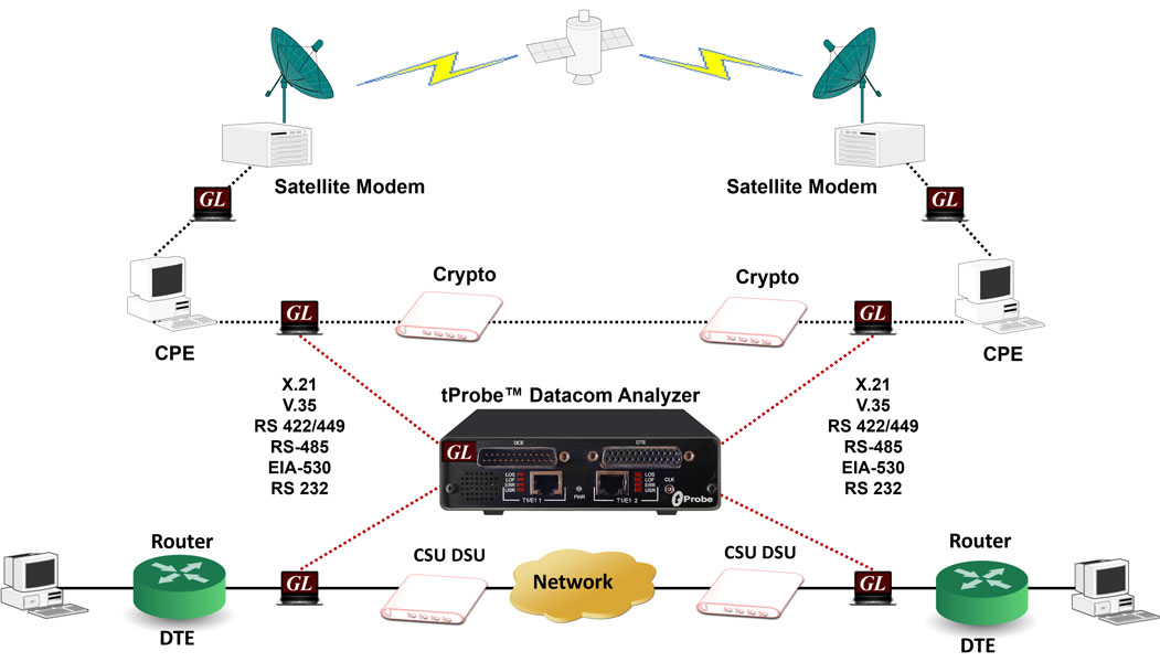
Overview
Data Communications refers to the transmission of digital information over a communication channel. The data transmission types include either parallel or serial type transfer. When data transmission is required over long haul, it is feasible to use serial type transfer as it allows high data rates with cost efficiency. Serialized data can be of asynchronous or synchronous in nature.
Different transmission mediums have evolved over the years for transmitting data signals, either electrically, optically, or as radio waves. The selection of the transmission medium largely depends on the distance over which data signals needs to be transferred, data rates, cost, and reliability.
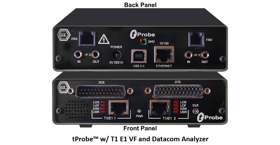
GL's Datacom Analyzer/Emulator is an optional board available with GL's tProbe™ T1 E1 Analyzer USB Unit. The portable tProbe™ T1 E1 and Datacom Analyzer is designed for test and verification of data communications equipment and circuits – specifically serial interfaces that provide clock, data, and control signals. These are commonly encountered in military links, satellite circuits, WAN, and data modem interfaces. Software selectable modes are provided to emulate DTE, DCE and non-intrusive monitoring for both synchronous (sync), and asynchronous (async) modes. Interface standards X.21, V.24, V.35, RS-449, RS-485, EIA-530 and EIA-530A are supported. Various cables are provided for these interfaces to make testing convenient.
tProbe™ Datacom Analyzer/Emulator is now enhanced to support the Windows Client/ Server (WCS) scripted test software, providing the capability of remote operation, automation, and multi-site connectivity.
GL offers two versions of the tProbe™ T1 E1 Datacom Analyzer:
- The first version is designed for domestic use and operates with AC mains power
- The second version, CE approved, is powered by USB 3.0
Main Features
- Supported Line interfaces - V.24, V.35, X.21, RS-449, RS-485, EIA-530 and EIA-530A
- Allows user to define custom frequency data rate for all encoding options
- Supports signal activity on the Datacom DCE and DTE interfaces along with the frequency measurements for each port
- Supports PPP, HDLC, and Frame Relay protocol analysis over serial data lines
- Supports HDLC Tx/Rx Test and HDLC Impairment Utility
- Sync BER from 300 b/s to 16.384Mbps
- Async BER from 75 b/s to 115.2Kbps
- DTE or DCE emulation mode
- SYNC clock source and sense selection
- Supports NRZ, FM0, FM1 and Differential Manchester encoding schemes
- Manchester IEEE BER from 75 b/s to 1.024 Mbps
- Manchester GE Thomas BER from 75 b/s to 1.024 Mbps
- Differential Manchester BER from 75 b/s to 1.024 Mbps
- Manchester FM0 and FM1 BER from 75 b/s to 1.024 Mbps
- NRZI BER from 0.5Mbps to 10Mbps
- Precision Delay Measurement, Unframed/Framed, Tx/Rx loopback and Error Insertion applications are provided for intrusive testing
- Supports Full/Fractional Bit Error Rate Testing with detailed logging
- With additional licensing Client Server (WCS) module also supports Enhanced BER testing
- A variety “Basic Applications” and “Optional Applications” are available with Datacom cards
Typical Application
- Bidirectional monitoring with Y-adapter cable
- Monitor control leads, frequency
- DTE/DCE emulation for end-to-end testing of data networks, bidirectional monitoring for a greater level of troubleshooting for data networks
DTE Emulation Mode
DCE Emulation Mode
Monitoring Data Communication Lines
- Verifying end-to-end transmission through DCE or DTE
Monitoring of Control Signals and Frequency
Displays the following signal activity on the Datacom DCE and DTE interfaces along with the frequency measurements for each port.
RXD: (Received Data)
This is the serial encoded data received by a DTE from a DCE which has in turn received from another source.
RXC: (Receive Complete)
The RXC bit will be set to HIGH(1) when data has been received and is available in the buffer.
TXC: (Transmit Complete)
The TXC bit is set to HIGH(1) when a transmission is completed and there is no other data to send.
CTS: (Clear to Send)
This is set true by a DCE to allow the DTE to transmit data. The DCE would use its CTS to prevent any transmission by the distant DTE.
RI: (Ring Indicator)
This signal is used for auto answer applications. DCE raises when incoming call detected used for auto answer applications.
DSR: (Data Set Ready)
This should be set true by a DCE whenever it is powered on. It can be read by the DTE to determine that the DCE is on line. In data acquisition application is generally false.
DCD: (Data Carrier Detect)
This is set true by a DCE when it detects the data carrier signal on the Datacom line.
Frequency
Displays operating Frequency in Hertz.
Monitoring Datacom Line Status
Monitoring Multiframes
This application permits viewing unframed data on a Datacom port. Approximately 2 seconds of data is captured for viewing. For Datacom systems, 16 frames are displayed per multiframe.
Monitoring Multiframes
Intrusive Test Applications
Bit Error Rate Test
The Bit Error Rate Test (BERT) application generates/detects Pseudo Random Bit Sequence (PRBS) for testing performance of data communication circuits.
Enhanced Bit Error Rate Testing (BERT)
Enhanced Bit Error Rate Testing (BERT)
The Enhanced Bit Error Rate Tester measures the correctness of data received on datacom according to the repetitive pattern file for a given transmission. The digital data in various fields such as digital circuits, mobile communications, antennas, digital broadcasting need to be monitored for error-free transmission. Bit Error Rate provides a figurative measurement of the number of erroneous bits received for the total number of bits transmitted. With GL’s powerful Bit Error Rate Tester, users can compare the bit/data pattern received against a known pattern in order to identify errors.
Precision Delay Measurement
Precision Delay Measurement measures the Round Trip Delay of a system. Sending a BER pattern with the insertion of an error bit and timing the reception of the error bit do the Round Trip Delay measurement. Measurement is precise and accurate to the microsecond level. A delay up to 8 seconds can be measured
Rx to Tx Loop back
This application is used in conjunction with a Bit Error Rate Test to verify the operation of Cards and Laptop units.
Automated VQuad™ Test Script Execution
Error Insertion
The Error Insertion application permits inserting single, fixed, automatic, random, and burst error into the incoming or outgoing bit stream.
Optional Applications
Record/Playback Applications
-
Record / Playback Disk Files
This optional software (XX020) permits record/playback to/from file across DTE/DCE interfaces. The three applications provided are: Playback from File, Automated Record Playback .

-
Record from multiple cards
This application permits capture of data being transmitted on (any one or both) Datacom analyzer to a file.
-
Automated Record Playback
The 'Automated Record/Playback (ARP)' application is an extremely versatile and rugged application incorporated in Datacom analyzer that makes it very easy for the user to run several transmit or receive operation tasks simultaneously.
Protocol Analyzers and Emulators
GL's protocol analyzers can be used to diagnose signaling problems quickly and effectively by analyzing traffic on multi-protocol signaling networks. It monitors signaling interactions in fixed, access and wireless networks. It analyzes multiple protocols like HDLC, PPP, and Frame Relay.
-
PPP Protocol Analysis
PPP analyzer captures and decodes host of PPP protocols exchanged between pairs of nodes over Serial Data Communications links. It provides useful analysis of the PPP, MLPPP, and MC-MLPPP protocols which includes distribution of protocols, protocol fields, frame lengths and frame status.The supported protocol standards in PPP Protocol analyzer are PPP, PPP SIGTRAN, IEC, IPCP, BCP, and more.
For more information on PPP supported standards visit PPP protocol analyzer webpage.
Automated VQuad™ Test Script Execution
-
HDLC Protocol Analysis
visit HDLC protocol analyzer webpage.
GL's HDLC protocol analyzer provides the capability to capture, and analyze HDLC data on a Serial Data Communications links.
Protocol standards supported for HDLC are LAPF, LAPD, LAPD+IP, LAPX+IP, X.25, Cisco HDLC Protocols.
For more information on HDLC supported standards
Automated VQuad™ Test Script Execution
-
Frame Relay Protocol Analysis
GL's Frame Relay Protocol Analyzer can be used to analyze and decode frames conforming to Q.921, Q.922, LAPF, Frame Relay Forum standard -FRF.9 and FRF.12, Multiple Protocol Encapsulation, LCP RFC1661, Q.933 SVC and LMI SNAP, PPP, IP, SMTP, POP3 and so on.
For more information on Frame Relay supported standards visit Frame Relay protocol analyzer webpage.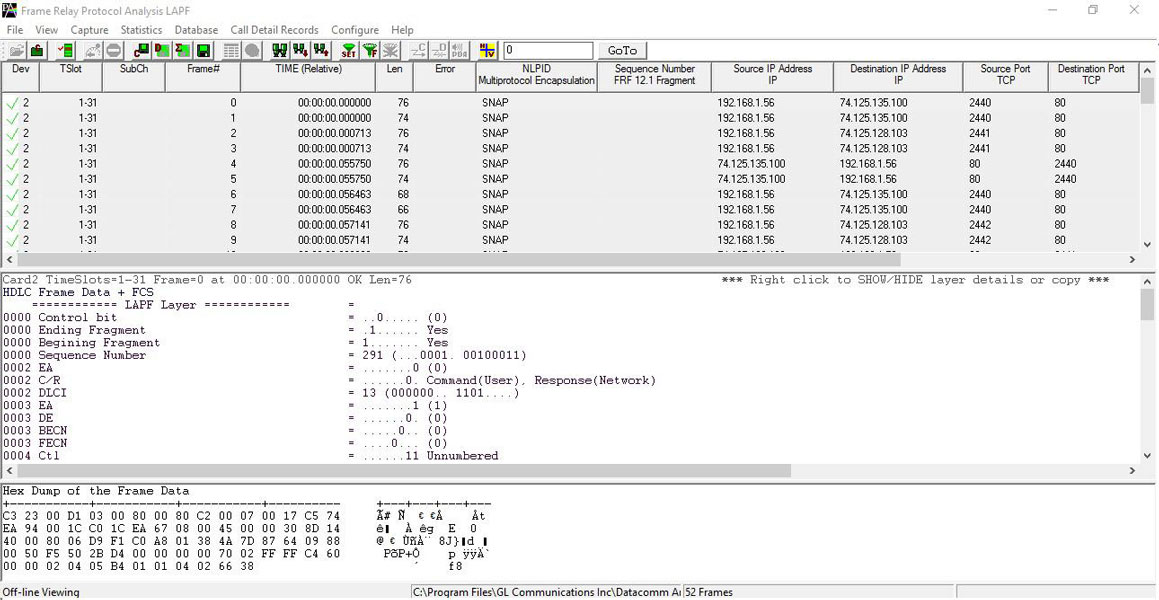
-
Client / Server applications allow the user (with an appropriate client) to operate analyzers remotely, write scripts for automation, or provide multi-client connectivity to a single Datacom analyzer. Now, Windows Client / Server available as a part of Basic Applications in Datacom Analyzer. GL provides sample-working clients in C++, VB, and TCL along with the server.
With additional licenses, WCS supports Enhanced BERT functionality, which measures the correctness of data received on Datacom against a repetitive fixed or pseudorandom pattern for the given transmission.
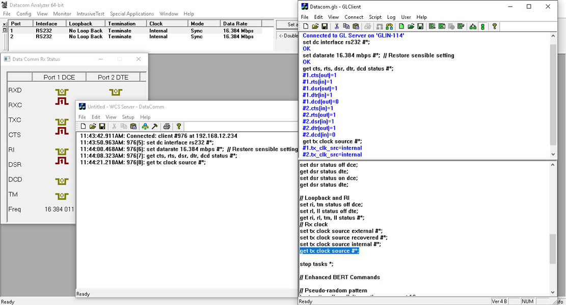
GLClient executing Enhanced BER Testing Script
Device Certification:
Device is RoHS compliant and the tests were conducted by an independent laboratory.
Council Directive:
- EMC 2014/30/EU
- LVD 2014/35/EU
Safety Standards:
- EN61326-1: Ed. 2.0 (2012-07) {EN 61326-1: 2013}: Electrical equipment for measurement, control and laboratory use – EMC requirements – Part 1: General requirements
- CISPR 11:2015, Limits and methods of measurement of electromagnetic disturbance characteristics of industrial, scientific and medical (ISM) radio-frequency equipment, Amendment 1:2016
- IEC 61000-3-2:2014, Electromagnetic compatibility (EMC) – Part 3-2: Limits – Limits for harmonic current emissions (equipment input current ≤ 16A per phase)
- IEC 61000-3-3:2013, Electromagnetic compatibility (EMC) – Part 3-3: Limits – Limitation of voltage changes, voltage fluctuations and flicker in public low-voltage supply systems, for equipment with rated current ≤ 16 A per phase and not subject to conditional connection
- IEC 61000-4-2:2008, Electromagnetic compatibility (EMC) – Part 4-2: Testing and measurement techniques – Electrostatic discharge immunity test
- IEC 61000-4-3:2006, Electromagnetic compatibility (EMC) – Part 4-3: Testing and measurement techniques – Radiated, radiofrequency, electromagnetic field immunity test, Amendment 1:2007, Amendment 2:2010
- IEC 61000-4-4:2004, Electromagnetic compatibility (EMC) – Part 4-4: Testing and measurement
- IEC 61000-4-5:2006, Electromagnetic compatibility (EMC) – Part 4-5: Testing and measurement techniques – Surge immunity test
- IEC 61000-4-6:2008, Electromagnetic compatibility (EMC) – Part 4-6: Testing and measurement techniques – Immunity to conducted disturbances, induced by radio-frequency fields
- IEC 61000-4-11:2004, Electromagnetic compatibility (EMC) – Part 4-11: Testing and measurement techniques – Voltage dips, short interruptions, and voltage variations immunity tests
- IEC 61010-1:2010 CE Marking -LVD
Product Technical Comparison
| Feature | Requirement | mTOP™ T1 E1 Datacom Rackmount |
|---|---|---|
| Portability | Portable or Fixed location | Rackmount |
| Physical Connection | No of EIA-530 ports | 2 |
| Port Configuration | I/O interface | V.35, EIA_530, RS232, EIA_530A, RS449/RS-442 and X21 |
| DCE/DTE | DTE/DCE | |
| Manual RTS and DTR | Compliant | |
| Data inversion | Compliant | |
| Line termination | Compliant | |
| System Configuration | Full duplex Half duplex Self loop |
Full Duplex – Compliant Half Duplex – Device supports Monitor and Bridge mode Self Loop – Compliant |
| Data Rates | Async: 50 to 20k | Async: 75 bps to 115.2 Kbps and user configurable frequency |
| Sync: 50 to 10M | Sync: 300 bps to 16.384 Mbps and user configurable frequency | |
| Test Path | End-to-End | Compliant |
| Loopback | Compliant | |
| Monitoring | Compliant | |
| Test Patterns | Fixed patterns: MARK SPACE 1:1 1:7 1:16 2:8 3:24 |
Supported Patterns : All Ones, All Zeros, 1:1, 1:7, 3 in 24, CSU Loop-Up (00001), CSU Loop-Down (001), NIU Loop-Up (11000), NIU Loop-Down (11100) and User Defined Pattern (3 bits to 32 bits) |
| Pseudo random patterns: 63 (26-1) 511 (29-1) 2047 (211-1) 32,767 (215-1) 1,048,575 (220-1) 8,388,607 (223-1) QRSS |
Supported Patterns : 26-1, 29-1, 211-1, 215-1, 220-1, 223-1 and QRSS |
|
| Error Insertion | Manual | Compliant |
| Automated | Single : Single at time intervals (1 sec resolution) 10-2 to 10-9 bit error rate | |
| Messages | User message: Up to 1024 bits | Compliant |
| Binary/ASCII | Compliant | |
| Test Interval | Continuous and 10 to 100M bits | Ability to test continuously with the BERT application and BERT timed test with WCS |
| Line Data Encoding | Line encoding: FM0 FM1 Manchester Differential Manchester |
|
| Timing | Jitter measurement | Not Compliant |
| External clock | Compliant | |
| Internal clock accuracy: +5ppm | +/- 1 ppm Internal Clock | |
| Internal clock drift +5ppm/yr | +/- 1 ppm Internal Clock | |
| Data clock: Synchronous Recovered |
Compliant | |
| Round Trip Delay (RTD) | RTD: 1 microsecond or better |
Micro Second Precision |
| User Interface | Display | Windows based software application |
| Displays: RTS CTS DTR DSR LOS |
Supported | |
| External Links | Ethernet | Supported |
| USB | Supported | |
| Wireless | Not Supported | |
| Internal Battery | N/A | Not Compliant |
| Environmental Impact | RoHS REACH |
RoHS Compliant |
| Operating Environment | Temperature: 0oC to 35oC |
0° C to 50° C |
| Humidity: 20% to 90% |
10% - 95% Humidity, Non-condensing | |
| EMC/EMI: EN55032 EN55035 |
EMC 2014/30/EU LVD 2014/35/EU |
|
| Safety: AS/NZS 60950-1 AS/NZS 62368-1 |
IEC 61010-1:2010 CE Marking -LVD |
|
| Operating voltage: 230VAC nom. |
Operates on USB 2.0 and External Power supply 5V.2A |
Supported Datacom Interfaces
RS232C
It is a standard interface for serial data for connecting DTE to DCE computer serial ports.
RS-423
It is a higher speed unbalanced interface similar to RS-232C. The Datacom board supports this with RS-232C interface setting.
RS-449
It is a high speed serial data communication interface. This interface used unbalanced or pairs of signals to transmit and receive clock and data. This interface typically uses a 37 pin connector.
RS-422/RS-485
It is similar to the RS-449 standard with changes only to the logic levels. This is sometimes used with a multi drop configuration of up to 10 receivers with 1 transmitter. Difficult to setup but can fill low cost reliable data communications.
V.35
It is another high speed serial data communication interface. This interface also uses unbalanced or pair of signals to transmit and receive clock and data. This interface typically uses a 35 pin connector.
Datacom Async Configuration
RS-530
It is another high speed serial data communication interface. It is a common interface used to replace a 25 pin connector instead of using the RS-449 DB-37 or V.35 connectors.
ASYNC Configuration
Configuration functionality allows to configure various Tx/Rx parameters such as Data Bits, Parity Bits, and Stop Bits.
Frequencies of Supported Encoding Options |
|||
| Mode | Frequency | ||
| Low | High | ||
|---|---|---|---|
| Async | 75 bps | 115.2 Kbps | |
| Sync | 300 bps | 16.384 Mbps | |
| Manch IEEE | 75 bps | 1.024 Mbps | |
| ManchGE T | 75 bps | 1.024 Mbps | |
| NRZI | 0.5 Mbps | 10 Mbps | |
| ManchDiff | 75 bps | 1.024 Mbps | |
| ManchFM0 | 75 bps | 1.024 Mbps | |
| ManchFM1 | 75 bps | 1.024 Mbps | |
Loopback Types
- No Loopback - This option disables any existing loopback conditions.
- Outward Loopback - In this configuration the data sent from the CSU are received by the Datacom interface and are immediately retransmitted to the CSU.
- Diagnostic (Input + Output) Loopback - Loops the internal transmit clock and data to the internal receive clock and data along with looping the external clock and data back to the incoming device.
- Cross-port Loopback - It takes the Tx data from the DTE and places it on the Rx of the DCE. It also takes Rx data from the DCE and places it on the Tx of the DTE.
RS 530 Pin Configurations on tProbe™ Datacom Analyzer Unit
| RS-530 Connections (DCE) Male Connector | ||||
| Pin | Signal | Direction | Description | |
|---|---|---|---|---|
| 1 | CHGND | Chassis Ground | Chassis Ground | |
| 2 | RD+ | Input to tProbe | Receive Data + | |
| 3 | TD+ | Output from tProbe | Transmit Data + | |
| 4 | CTS+ | Input to tProbe | CTS Receive + | |
| 5 | RTS+ | Output from tProbe | RTS Transmit + | |
| 6 | DTR+ | Output from tProbe | DTR Transmit + | |
| 7 | GND | Signal Ground | Ground | |
| 8 | DCD+ | Output from tProbe | DCD Transmit + | |
| 9 | TT- | Output from tProbe | Transmit Clock - | |
| 10 | DCD- | Output from tProbe | DCD Transmit - | |
| 11 | RT- | Input to tProbe | Receive Clock - | |
| 12 | ST- | Output from tProbe | Secondary Timing - | |
| 13 | RTS- | Output from tProbe | RTS Transmit - | |
| 14 | RD- | Input to tProbe | Receive Data - | |
| 15 | ST+ | Output from tProbe | Secondary Timing + | |
| 16 | TD- | Output from tProbe | Transmit Data - | |
| 17 | TT+ | Output from tProbe | Transmit Clock + | |
| 18 | TM | Input to tProbe | Test Mode | |
| 19 | CTS- | Input to tProbe | CTS Receive - | |
| 20 | DSR+ | Input to tProbe | Data Set Ready + | |
| 21 | RI | Input to tProbe | Ring Indicator | |
| 22 | DTR- | Output from tProbe | DTR Transmit - | |
| 23 | DSR- | Input to tProbe | Data Set Ready - | |
| 24 | RD+ | Input to tProbe | Receive Clock+ | |
| 25 | LL | Output from tProbe | Local Loop | |
| RS-530 Connections (DTE) Female Connector | ||||
| Pin | Signal | Direction | Description | |
|---|---|---|---|---|
| 1 | CHGND | Chassis Ground | Chassis Ground | |
| 2 | TD+ | Output from tProbe | Transmit Data + | |
| 3 | RD+ | Input to tProbe | Receive Data + | |
| 4 | RTS+ | Output from tProbe | RTS Transmit + | |
| 5 | CTS+ | Input to tProbe | CTS Receive + | |
| 6 | DSR+ | Input to tProbe | Data Set Ready + | |
| 7 | GND | Signal Ground | Ground | |
| 8 | DCD+ | Input to tProbe | DCD Transmit + | |
| 9 | RT- | Input to tProbe | Receive Clock - | |
| 10 | DCD- | Input to tProbe | DCD Transmit - | |
| 11 | TT- | Output from tProbe | Transmit Clock - | |
| 12 | RTC- | Input to tProbe | Secondary Receive Clock- | |
| 13 | CTS- | Input to tProbe | CTS Receive - | |
| 14 | TD- | Output from tProbe | Transmit Data – | |
| 15 | RTC+ | Input to tProbe | Secondary Receive Clock+ | |
| 16 | RD- | Input to tProbe | Receive Data - | |
| 17 | RT+ | Input to tProbe | Receive Clock + | |
| 18 | LL | Output from tProbe | Local Loop | |
| 19 | RTS- | Output from tProbe | RTS Transmit + | |
| 20 | DTR+ | Output from tProbe | DTR Transmit + | |
| 21 | RL | Input to tProbe | Remote Loop | |
| 22 | RI | Input to tProbe | Ring Indicator | |
| 23 | DTR- | Output from tProbe | DTR Transmit - | |
| 24 | TT+ | Output from tProbe | Transmit Clock + | |
| 25 | TM | Input from tProbe | Test Mode | |
Resources
Please Note: Datacom Analyzer/Emulator is an optional board available with tProbe™ T1 E1 Analyzer USB Unit.
| Item No. | Item Description |
| PTE001 | tProbe™ Analyzer (Dual Ports) |
| PTE002 | Datacom Only Analyzer Software for tProbe™ (with DTE and DCE Ports) requires PTE025; Basic T1 or E1 software is NOT required Accessories By default, includes 2-wire FXO and FXS Optional Board (only Hardware) (1) USB 2.0 Cable (1) 5 V power adapter (1) Short Cross over cable (1) RJ 11 cable (2) |
| PTE025 | Data Communications Board for Interfaces RS-232, RS-449, EIA-530, V.35, and many others Accessories By default, includes 2-wire FXO and FXS Optional Board (only Hardware) (1) USB 2.0 Cable (1) 5 V power adapter (1) Short cross over cable (1) RJ-11 cable (2) |
| Related Software | |
|---|---|
| PTE020 | Datacom Record/Playback File Software (Including Automated Continuous Capture and Automated Record Playback Software) |
| PTE090 | Datacom T1 or E1 Real-Time HDLC Decode/Store/Impairment/Rx-Tx Test Applications |
| PTE130 | Datacom Real-time Frame Relay Analysis |
| PTE135 |
Datacom T1 or E1 PPP Analyzer |
| Datacom Board Cables | |
| DBC001 | DB-25-3-M/M ASSY -DB25 3FT Male to Male (RS-232/RS530 DTE) |
| DBC002 | DB-25-3-F/F ASSY - DB25 3FT Female to Female (RS-232/RS530 DCE) |
| DBC003 | DB-25-3-M/F ASSY -DB25 3FT Male to Female (Loopback) |
| DBC004 | DB25F-3-DB37F ASSY - DB25 Female to DB37 Female 3FT (RS-449 DCE) |
| DBC005 | DB25M-3-DB37M ASSY - DB25 Male to DB37 Male 3FT (RS-449 DTE) |
| DBC006 | DB25F-3-V.35F ASSY - DB25 Female to V.35 Female 3FT (V.35 DCE) |
| DBC007 | DB25M-3-V.35M ASSY - DB25 Male to V.35 Male 3FT (V.35 DTE) |
| DBC008 | DB25F-3-DB15F ASSY - DB25 Female to DB15 Female 3FT (X.21 DCE) |
| DBC009 | DB25M-3-DB15M ASSY - DB25 Male to DB15 Male 3FT (X.21 DTE) |
| DBC010 | DB25F-3-DB15F ASSY - DB25 Female to DB15 Female 3FT (X.27 DCE) |
| DBC011 | DB25M-3-DB15M ASSY - DB25 Male to DB15 Male 3FT (X.27 DTE) |
| DBC012 | RS-530Y ASSY - RS-530 Y Cable |
| Related Hardware | |
| LTS010 | LinkTest™ Dual E1 Accessories 15 - 18 V Power Adapter (1) Carry pouch (1) |
| LTS011 | LinkTest™ DualE1 with DataCom ports |
| LTS012 |
LinkTest™ DualE1 with DataCom ports and Jitter/Wander and Pulsemask |
*Specifications are subjected to change