MAPS™ SS7 Protocol Emulator
(SS7/ISUP Protocol Emulation over TDM)
Background
SS7 (Signaling System Number 7) defined by the International Telecommunication Union (ITU- T) is a globally adopted protocol for out-of-band signaling systems.
The network elements involved in SS7 networks are SSPs (Signaling Switching Points), STPs (Signaling Transfer Points) and SCPs (Signaling Control Points). These elements ensure signaling integrity and availability even if one or more signaling links fail.
The SS7 network manages calls by identifying end-to-end addressing and from there controls all the routing judgments necessary for a seamless operation.
ISUP is a part of the complex signaling system SS7 that are used to set up and release calls through the PSTN. ISUP end-to-end signaling is transported directly over MTP3 or SCCP levels.
Overview
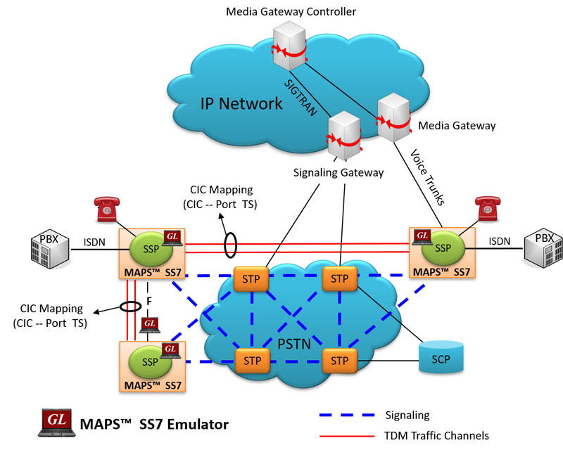
GL's Message Automation & Protocol Simulation (MAPS™) designed for SS7 simulation over TDM (T1 E1) can simulate Service Switching Point (SSP). The ISUP signaling specification conforms to ITU-T and ANSI standards. The tester supports testing network elements, error tracking, regression testing, conformance testing, load testing/call generation and generation of high volumes of ISUP traffic. MAPS™ SS7 functionality covers the ITU and ANSI variant of SS7 implementing MTP2, MTP3, and ISUP protocols. It is able to run pre-defined test scenarios against ISUP test objects in a controlled & deterministic manner.
The application is available as
- MAPS™ SS7 Emulator (Item # XX649)
- MAPS™ SS7 Conformance Scripts (Item # XX647)
MAPS™ SS7 Conformance Scripts (XX647) is designed for conformance tests and functional tests, where test objects can be accurately, reliably and comfortably validated for compliance with ITU-T standard Q.761-764 and Q.784. It is suitable for manufacturers, network operators and service providers to address all stages of the development cycle, regression testing through to type approval, acceptance testing.
The application gives the users the unlimited ability to edit SIP messages and control scenarios (message sequences). "Message sequences" are generated through scripts. "Messages" are created using message templates
With the purchase of additional licenses (xx610, xx620, xxFT0) traffic can be simulated over T1 E1 interfaces. Supported traffic includes transmission and detection of TDM digits, voice files, single tone, dual tone, speech and FAX. Also supports various traffic events simulation during the course of a call, which is listed below:
TDM Traffic Events – digits, tones, files, speech, fax
- Send, and Detect Tones, Digits, File, Test Tone, Silence and verify speech bearer
- Stop Send Digits, File, Tone
- Stop Send - Stops Transmission of Tone
- Detect different tone types - dial tone, special dial tone, stutter dial tone, special information tone, call waiting, call in progress tone, reorder tone, busy tone, congestion tone, confirmation tone, howler tone, and ring-back tone
- Set region for call progress tones (Busy, Call Waiting, Dial, Ring, Congestion, Special Dial, Special Information) detection
- Send /Receive fax image (TIFF format) file from/to the specified location.
User can remotely perform all MAPS™ SS7 functions using MAPS™ client-server functionality (requires additional license), which includes scripting through a Command Line Interface (CLI) such as the Python, Java, VBScript, and TCL clients. Signaling and traffic functionalities such as start test bed setup, load scripts and profiles, apply user events such as send digits/file/tones, detect digits/file/tones, dial, originate call, terminate call, start and stop traffic and others can be performed remotely. User can also generate and receive calls through commands. The client application includes a dll file, a packaged library that enables communication with the Server from the client environment, which is distributed along with MAPS™ CLI Server application.
GL also provides an independent GUI based SS7 protocol analyzers (optional application – xx120) for online capture and decode of the signaling in real-time both during tests and as a stand-alone tracer for live systems.
Supported Protocols Standards
 |
|
|||||||||||||||||||
ISUP Call Simulation
Typical ISUP Signaling Procedure
ISUP Call Messages
ISUP Call Generation and Reception
MAPS™ ISUP is configured as end-terminals in the network simulating the ISUP signaling call and handling TDM traffic – voice, file, digits, VF, FAX, IVR over the established call.

ISUP Basic Call Generation
ISUP Call Reception
ISUP Conformance
As an example, MAPS™ ISUP Conformance is configured (SP B) with GL’s DCOSS (DUT). The purpose of this conformance test is to verify that on receipt of a Reset Circuit message SP A (DUT) will respond by sending a Release Complete message.

Reset of circuits Conformance
The answer call conformance script is set against the Reset Circuit message in Incoming Call Handler Configuration, which is triggered when MAPS™ ISUP receives a release message with a given cause and the correct indication is given to the calling party. The call will be immediately released by the outgoing signaling point verifying the Unsuccessful call setup. The suggested causes are: unallocated number, no circuit available, switching equipment, and congestion.
Unsuccessful Call Setup Conformance
A Typical MAPS™ SS7 Test System
A typical MAPS™ SS7 consists of:
- A Python/Java interface communicating over TCP/IP to a Rack PC with T1 E1 Analyzer Software
- The Rack PC consists of MAPS™ Client IFC, MAPS™ CLI Server, T1 E1 Analyzer Software (including Windows Client Server software) and a Dual T1 E1 Card
- A patch panel for RJ-11 connections to the outside world (DUT)
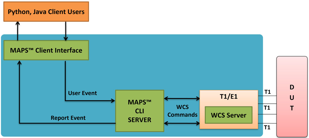
- Python/Java Client – Acts as User Interface, which executes Python/Java Scripts
- MAPS™ Python/Java Interface (MAPS Client IFC) – acts as an interface between MAPS™ CLI Server and its Python/Java client Python. It interprets the Python/Java commands and forms the appropriate command as understood by MAPS CLI Server and vice versa.
- MAPS™ CLI Server is an executable that inherits all features of MAPS™ without GUI. It listens to a TCP message socket to receive and execute commands from client and sends the responses back to client.
T1 E1 Windows Client Server - Windows Client/Server software performs all SS7 emulation primitives including signaling, tone detection, call progress signals, file transfer, and many more functions.
In CLI, MAPS™ Server constitutes two server modules, namely MAPS™ CLI server and GL WCS server.
- MAPS™ CLI Server
MAPS™ CLI Server is an executable which inherits all features of MAPS™ without the graphical user interface. Instead it listens to TCP message socket to receive and execute commands from the client and sends the responses back to the client. - GL's Windows Client Server
GL's Windows Client/Server software allows the user of T1 E1 analysis cards the capability of remote operation, automation, and multi-site connectivity.
Python client recieves report event from the CLI server as shown in the below screenshot.
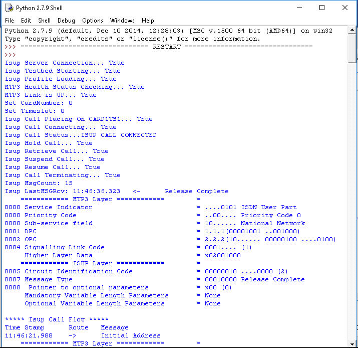
Python client receives report event WCS Server Log
Resources
Please Note: The XX in the Item No. refers to the hardware platform, listed at the bottom of the Buyer's Guide, which the software will be running on. Therefore, XX can either be ETA or EEA (Octal/Quad Boards), PTA or PEA (tProbe Units), XUT or XUE (Dual PCIe Express) depending upon the hardware.