LTE eGTP Interface Emulator
Simulation of evolved- GPRS Tunnelling Protocol (GTP) allowing both user traffic (GTPv2-U) and signaling (GTPv2-C) to traverse through the GTP tunnel across the various S(x) interfaces.
Brochure Request a Demo / Quote
Background
eGTP, also called evolved- GPRS Tunnelling Protocol (GTP) or GTP version 2 (GTPv2), is primarily used in LTE for exchanging user traffic over GTP tunnels across the various S(x) interfaces as shown in the diagram above. GTPv2 allows for both user traffic (GTPv2-U) and signaling (GTPv2-C) to traverse through the tunnel.
GTPv2-C is used to control signaling for bearer management between Mobility Management Entity (MME), Serving Gateway (SGW) and the Packet Data Network (PDN) Gateway (PGW) elements in an EPC network. GTPv2-C protocol is used over S3, S4, S5, S8, S10, S11 and S16 interfaces. GTPv2-U is used to identify the transport bearer and carry encapsulated packets through the identified bearer. GTPv2-U protocol is used over S1-U, X2, S4, S5, and S8 interfaces.
The user (UE) has very high-speed RF connection to the nearest local tower. This high-speed connection is always ON, as long as the mobile is powered up. LTE is an all IP infrastructure with service priority built in – audio and video are given priority. All necessities like IP address, authentication, and security are validated. Instant resources over RF (the air) and IP (internal network) are made available depending on what the user is attempting to do. Also, LTE is designed for compatibility with older 2G and 3G mobile systems.
LTE S11 and S5/S8 network elements include MME (to handle signaling of control plane), Serving gateway and Public Data Network (PDN) gateway (to handle mobility management tasks within LTE and other radio networks) as depicted in the picture above.
Overview
GL’s Message Automation & Protocol Simulation (MAPS™) designed for testing LTE – eGTP interfaces (S3, S4, S5, S8, S10, S11 and S16) can simulate MME (Mobility Management Entity), SGW (Serving Gateway) and PDNGW (PDN Gateway) as defined in specification 3GPP TS 29.274 Evolved GPRS Tunnelling Protocol for Control Plane (eGTP-c).
Additionally, MAPS™ LTE eGTP can support simulation of user-plane packet (GTPv2-U) traffic in LTE network with support of Mobile traffic Core - GTP (ETH101) application and user-plane Gateway traffic with support of Mobile Traffic Core – Gateway (ETH102) application. eGTP-c (i.e., GTPv2) supports path and tunnel management procedures within LTE network.
The application is available as
- MAPS™ - LTE-eGTP (Item # PKS142) for eGTP interfaces
The application gives the users the unlimited ability to edit eGTP messages and call scenarios (message sequences). "Message sequences" are generated through scripts. "Messages" are created using message templates.
GL has enhanced its MAPS™ protocol emulation tool to simulate multi-protocol and multi-interfaceoffering a complete range of test solutions, covering the entire 2G, 3G, and 4G network.
By mimicking real-world customer behavior in lab environments, our solutions allow mobile operators and equipment manufacturers to verify their wireless networks before deployment. In other words, one can setup a virtual real-time network simulating all the network elements using “MAPS 4G Wireless Lab Suite”. The test suite supports simulation of S1-MME, S11, S5/S8, and other required eGTP interfaces.
GL also provides a GUI based LTE Analyzer for on-line capture and decode of the signaling in real-time both during tests and as a stand-alone tracer for live systems.
Main Features
- Setup a virtual real-time network simulating 4G-LTE network elements using ‘MAPS™ 4G Wireless Lab Suite’
- Simulates MME, SGW and PDN GW elements in the LTE eGTP interface
- Supports both Control Plane and User-plane simulation across different interfaces
- Supports Path Management and Tunnel Management procedures over eGTP interfaces
- Massive UE simulation (up to 500000) with Auto generation feature for high density load testing
- Generates and responds to hundreds of UE Signaling (Load testing)
- Generates and process GTP-C messages (valid and invalid)
- Supports GTP Traffic (GTP User Plane Data) which includes: verification like HTTP traffic generation capability - requires additional licensing ‘ETH101’
- Option to offload GTP traffic to Gateway (GGSN)- requires additional licensing ‘ETH102’
- High-volume eGTP-u (User Plane) traffic simulation possible with support of ‘Packet Load’ appliance; both 4Gbps and 40Gbps variants are available to suit customer needs
- Automation, Remote access, and Schedulers to run tests 24/7
- Supports PacketLoad PCAP playback feature
Supported Protocols Standards
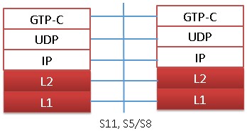 Control Plane for S11, S5/S8 Interface |
|
|||||||||
- GPRS Tunneling Protocol for the control plane (GTP C): This protocol tunnels signaling messages between MME and S-GW (S11)
- User Datagram Protocol (UDP): This protocol transfers signaling messages. UDP is defined in RFC 768 [26]
LTE eGTP Interface Procedure
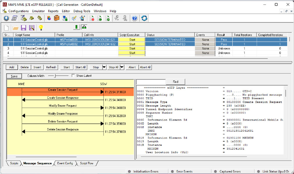
In LTE S11, S5/S8 and other eGTP interfaces, MAPS™ acts as either MME, SGW, or PDN GW while testing the other entities in the LTE eGTP network simulating the Path Management and Tunnel Management procedures. Path Management Procedure messages include Echo Request & Response, while Tunnel Management Procedure messages are Create / Delete Session Request/Response and Create/Modify/Update/Delete Bearer Request/Response, which are indicated in the following call flow:
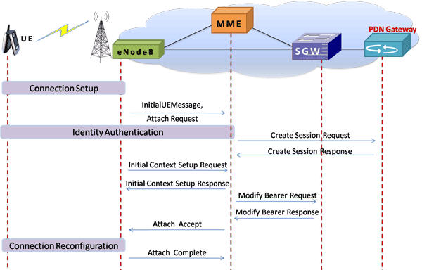
LTE - S11 and S5/S8 interfaces signaling scenario (messages between MME, SGW, and PGW)
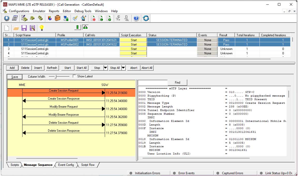
LTE S11 interface Call Control Procedure at MME Node
LTE S5/S8 interface Call Control Procedure at SGW Node
Resources
Please Note: The XX in the Item No. refers to the hardware platform, listed at the bottom of the Buyer's Guide, which the software will be running on. Therefore, XX can either be ETA or EEA (Octal/Quad Boards), PTA or PEA (tProbe Units), XUT or XUE (Dual PCIe Express) depending upon the hardware.
| Item No. | Item Description |
| PKS140 | MAPS™ LTE S1 Emulator |
| PKS139 | MAPS™ Diameter Emulator |
| PKS141 | MAPS™ LTE X2-AP Emulator |
| PKS142 | MAPS™ LTE eGTP Emulator |
| PKS146 | MAPS™ SGs Interface Emulation |
| GTP Mobile Traffic Options | |
|---|---|
| ETH100 ETH101 ETH102 ETH103 |
PacketCheck™ Mobile Traffic Core – GTP Mobile Traffic Core - Gateway Mobile Traffic Core - Gb |