MAPS™ UMTS for IuCS, IuH Interfaces Emulator
Simulation of UMTS protocol for IuCS interface over Asynchronous Transfer Mode (ATM), or Internet Protocol (IP) between Radio Network Controller (RNC) and Mobile Switching Center (MSC) handling CS traffic. IuH interface emulation between Femto Home NodeB (Femto Cell) and Femto Home Node Gateway (HnB-GW) elements.
Brochure Request a Quote
Background
Universal Mobile Telecommunications System (UMTS) is a 3rd generation mobile technology that can support greater data rates for voice and video data to the wireless end users. The underlying transport layer for UMTS can be Asynchronous Transfer Mode (ATM), or Internet Protocol (IP).
The UMTS network consists of the following elements -
- NodeB - supporting broadband mobile users
- Radio Network Controller (RNC) - manages radio resources (NodeBs) and routes traffic to circuit and packet switched elements
- Mobile Switching Center (MSC) - circuit switching element for voice
- Serving GPRS Support Node (SGSN) - packet switching element for data and video
- Femto Home NodeB (Femto Cell) - for enhanced coverage indoors and to offload the radio access network
- Femto Home Node Gateway (HnB-GW) - provides wired broadband interface
To emulate various components in IuCS and IuH interfaces of UMTS network, GL utilizes its MAPS™ architecture – a versatile platform for detailed emulation of a wide variety of protocols. MAPS™ supports emulation of many other protocols such as ISDN, SS7, GSM, LTE, SIP, Megaco, MGCP, SIGTRAN, and more.
IuCS and IuH over IP
GL’s Message Automation & Protocol Simulation (MAPS™) designed for UMTS IuH interface can simulate Femto Home Node B (HnB), and a Femto Home Node Gateway (HnB-GW) by generating RANAP and DTAP signaling messages over SCTP Transport layer. A femtocell is a small cellular base station designed for use in residential or small business environments. Femtocells can offload the RAN and provide better coverage, plus improved data download & upload speeds. IuH links Femto Access Point (HnB) and a Femto Gateway (HnB-GW).
MAPS™ UMTS IuCS can emulate the RNC (Radio Network Controller) and the MSC (Mobile Switching Center) by generating RANAP and DTAP signaling messages over SCTP. It includes ready scripts to simulate Location Update, Call Control MO (Mobile Originating), Mobile Terminating (MT), Mobile-to-mobile Voice Call/ SMS, SMS over active voice call, Supplementary Service Call and Handover (Relocation) procedures.
MAPS™ IuCS emulator is enhanced with CSV based UE/Subscriber configuration option to allow massive UE simulation. In real time scenario, there exists huge number of subscribers with unique UE parameters. The recent enhancements were introduced to MAPS™ UMTS IuCS and IuH test tools to include CSV subscriber profiles to dynamically generate number of subscribers with unique IMSI, TMSI, MSISDN and other key parameters in sequential order.
The application gives the users the unlimited ability to edit messages and control scenarios (message sequence). “Message sequences” are generated through scripts. “Messages” are created using message templates.
The application is available as
- MAPS™ - IuCS and IuH (Item # PKS160)
- MAPS™ IuCS and IuH HD (Item #PKS109, PKS160)
With the purchase of RTP Core license (PKS102), MAPS™ IuCS supports transmission and detection of various RTP traffic such as, digits, voice file, single tone, dual tones, IVR, FAX*, and Video*. With regular RTP traffic, the maximum Simultaneous Calls up to 2500, and Calls per Second up to 250 is achievable. Almost all industry standard voice codec supported.
GL’s MAPS™ IuCS is also available in High Density version (requires a special purpose network appliance and PKS109 RTP HD licenses). This is capable of high call intensity (hundreds of calls/sec) and high volume of sustained calls (tens of thousands of simultaneous calls/platform).
** Some of these traffic types requires additional licenses – contact GL for more information
MAPS™ IuCS emulator also supports Iu-UP (Iu User Plane Interface) protocol layer of the Radio Network with additional licensing (PKS103) to carry RTP traffic (AMR payload part) over Iu interface in support mode of operation for predefined SDU size.
MAPS™ IuCS ATM
GL's LightSpeed1000™ hardware platform (PCIe Card) with quad optical ports supports simulation of UMTS IuCs interface over ATM layer using MAPS™ IuCS ATM. The LightSpeed1000™ comes with software for overall monitoring, protocol analysis and emulation, and bert. The hardware can also be easily configured / programmed for delaying of ATM Cells or PPP packets.
MAPS™ IuCS ATM uses SSCOP server for establishing SSCOP links over which RANAP, ALCAP, and DTAP signaling will be carried for making calls. SSCOP Server is a GL's WCS based server module that provides SSCOP, AAL5 and AAL2 layer services. Following licenses are required for MAPS™ IuCS ATM:
- OC3 / STM1 MAPS UMTS IuCS over ATM, requires (Item # LTS220)
- OC3 / STM1 SSCOP Server (Item # LTS214)
- OC3 / STM1 AAL2 Traffic Core (Item # LTS217)
Over successfully established call, traffic can be generated. MAPS™ IuCS ATM internally uses AAL2 Traffic Generator for traffic generation. Various traffic types like Tone, Digits and File playback are supported.
Supported UMTS Analyzers and Simulators
- MAPS™ UMTS IuPS Simulators (PKS164)
- T1 or E1 UMTS Protocol Analyzer (XX165)
- Offline UMTS Protocol Analyzer (OLV165)
- OC-3 / STM-1 UMTS Protocol Analysis (LTS206)
- OC-12 / STM-4 UMTS Protocol Analysis (LTS306)
- PacketScan™ - UMTS IuCs Protocol Analysis over IP (PKV103)
Main Features
| IuCS Signaling over IP |
|
| IuCS Signaling over ATM |
|
| IuH Signaling over IP |
|
| Traffic Simulation |
|
| Statistics and Graphs |
|
Supported Protocols Standards
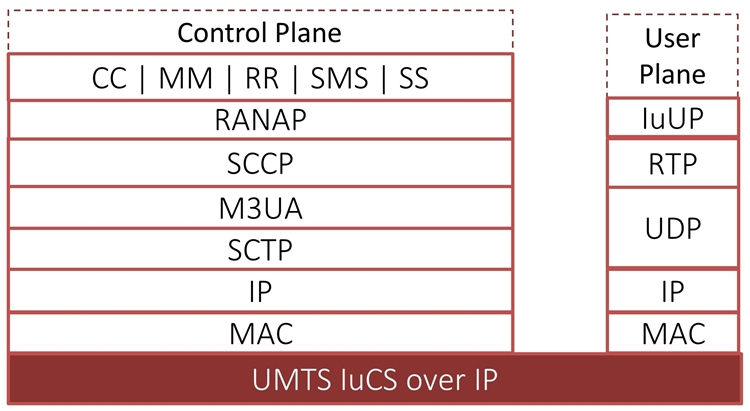
UMTS IuCS Protocol Stack
UMTS IuH Protocol Stack
| Supported Protocols | Specification Used |
| IuCS Interface | |
|---|---|
| SCCP | Q.713, CCITT (ITU-T) Blue Book |
| MTP3 | Q.703, ITU-T Blue Book |
| RANAP | 3GPP TS 25.413 V9.1.0 |
| MM / CC | 3GPP TS 24.008 V5.16.0 (2006-06) |
| RR | 3GPP TS 04.18 V8.13.0 |
| SMS | 3GPP TS 03.40 V7.5.0 & 3GPP TS 04.11 V7.1.0 GSM 03.38 version 7.2.0 Release 1998 |
| Iu-UP Iu User Plane Interface |
3GPP TS 25.415 |
| IuH Interface | |
| RUA | 3GPP TS 25468 V9.1.0 |
| RANAP | 3GPP TS 25.413 V9.1.0 |
| MM / CC | 3GPP TS 04.08 V7.17.0 |
| RR | 3GPP TS 04.18 V8.13.0 |
| SMS | 3GPP TS 03.40 V7.5.0 & 3GPP TS 04.11 V7.1.0 GSM 03.38 version 7.2.0 Release 1998 |
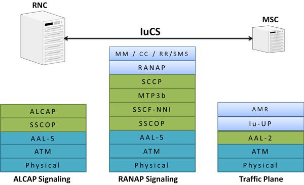
UMTS IuCS ATM base Protocol Stack
| Supported Protocols | Specification Used |
| IuCS ATM Interface | |
|---|---|
| SSCOP | ITU-T Q.2110 |
| MTP3b | ITU-T Recommendation Q.2210 |
| AAL Type 2 (ALCAP) | ITU-T Recommendation Q.2630.1 |
| RANAP | 3GPP TS 25.413 V9.1.0 |
| MM / CC | 3GPP TS 24.008 V5.16.0 (2006-06) |
| RR | 3GPP TS 04.18 V8.13.0 |
| SMS | 3GPP TS 03.40 V7.5.0 & 3GPP TS 04.11 V7.1.0 GSM 03.38 version 7.2.0 Release 1998 |
| Iu-UP Iu User Plane Interface |
3GPP TS 25.415 |
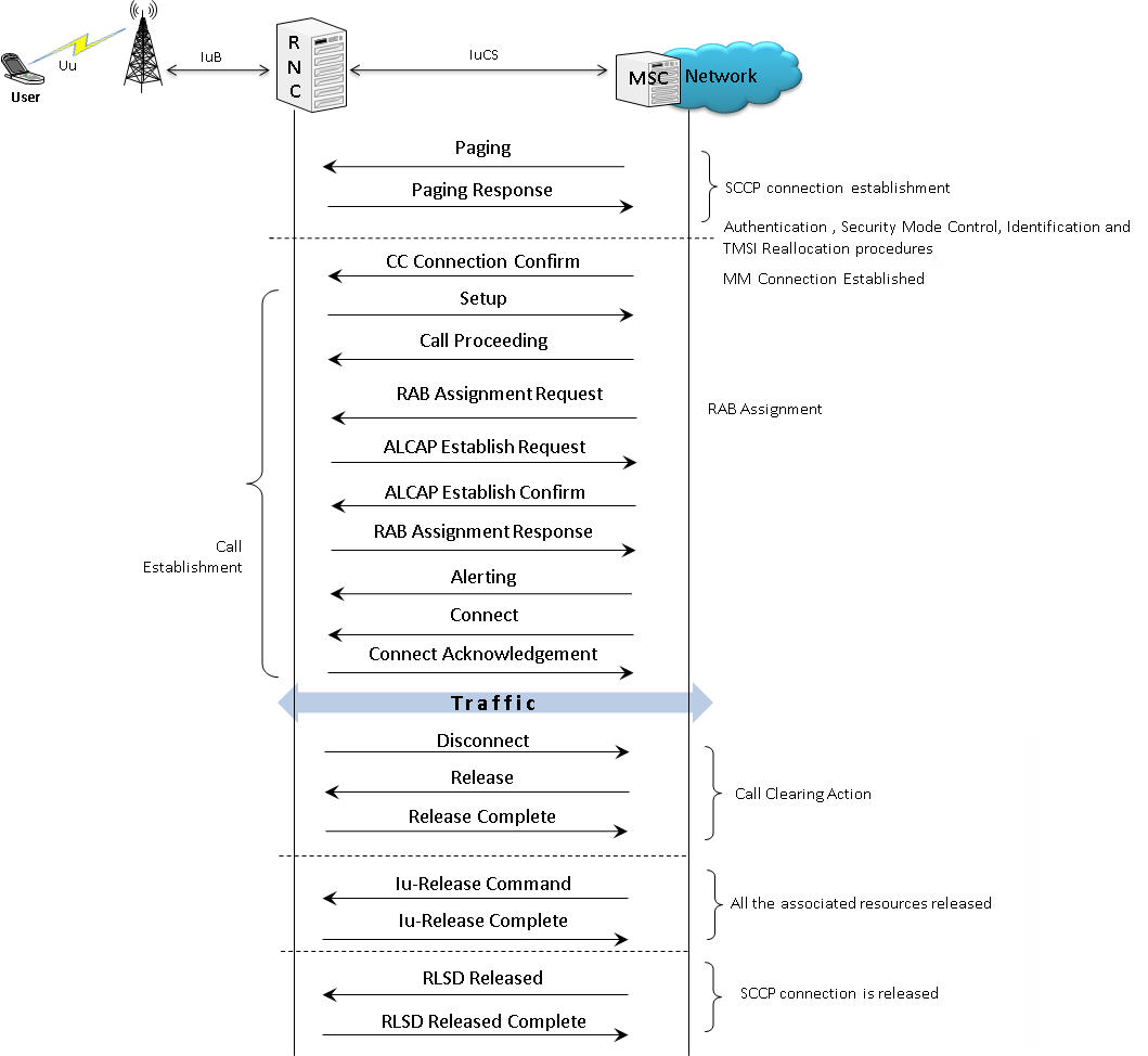
Call Simulation over IuCS ATM
In IuCS interface, MAPS™ acts as either RNC to test MSC (DUT) or MSC to test RNC (DUT) and simulates the following call control procedures:
Call Control MO - (Mobile Originating) Procedure

Typical Call Control MO Procedure
over IuCS ATM
Call Control MO Procedures at
RNC Node over IuCS ATM
Call Control MO Procedures at
MSC Node
over IuCS ATM
Mobile Terminating Call (MTC) Procedure
MAPS™ can be configured to act as Mobile Station Controller (MSC) to process the Mobile Terminating (MT) call procedure by initiating the Paging message with the Mobile Station (RNC). MAPS™ (RNC) then completes the call as in call control MT procedure.
Typical Call Control MT Procedure
over IuCS ATM

MT Procedure at RNC Node
over IuCS ATM
MT Procedure at MSC Node
over IuCS ATM
Call Simulation over IuCS IP
Call Generation option allows the user to simulate outgoing communications where an outgoing call is initiated by sending call control messages using proper scripts and profiles. MAPS™ application acts as either the Caller or resides at the network terminal acting as Callee.
In IuCS interface, MAPS™ acts as either RNC to test MSC (DUT) or MSC to test RNC (DUT) and simulates the following call control procedures:
SMS over active Mobile-Mobile Voice Call Simulation
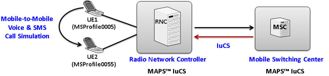
MAPS™ IuCS can be configured to simulate a simultaneous SMS call while an UE is on active mobile-to-mobile voice call with another UE.
To setup the test scenario, two profiles are configured to act as UE1 and UE2 at RNC for Location Update procedure. Once both the UEs are registered with the network, Mobile Originating call is initiated from UE1 following which the Mobile Terminating call is initiated automatically from MSC towards UE2, during which SMS call can be initiated by applying the “Send SMS” user event at either UE1 or UE2 to simulate SMS call while the original mobile-to-mobile voice call is still active.
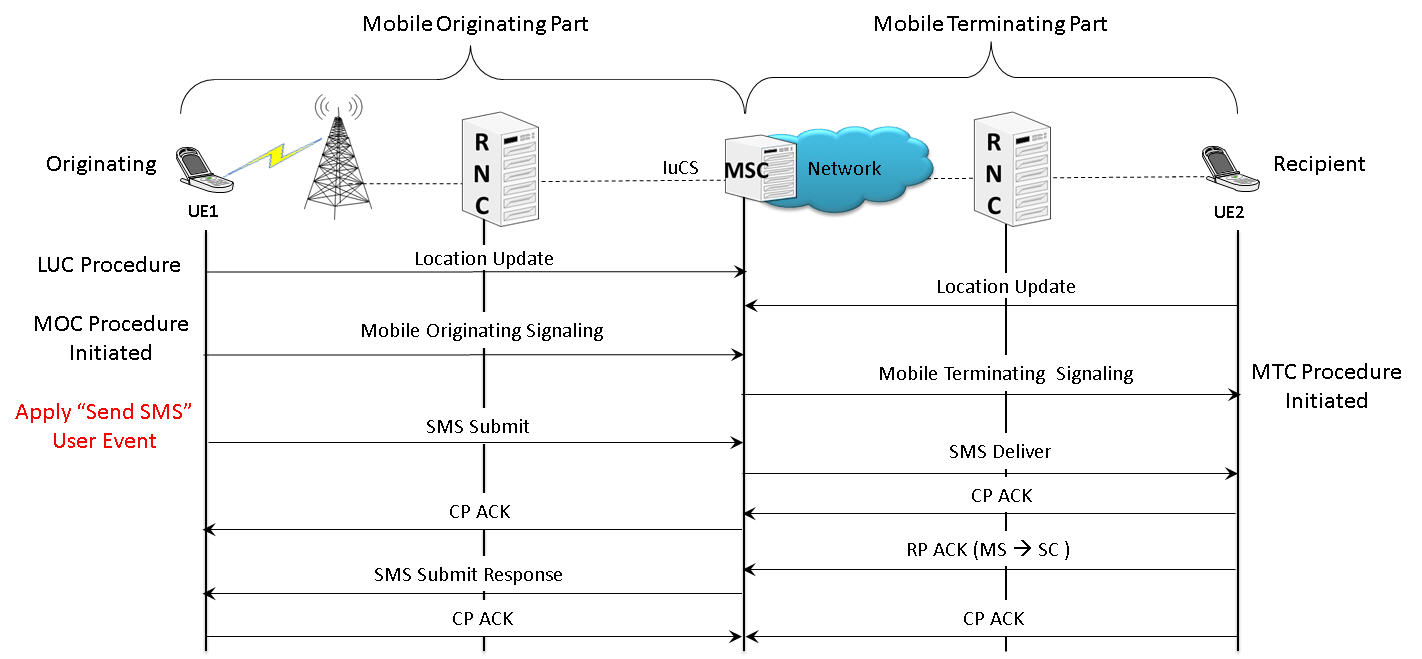
SMS over active Mobile-Mobile Voice Call Procedure
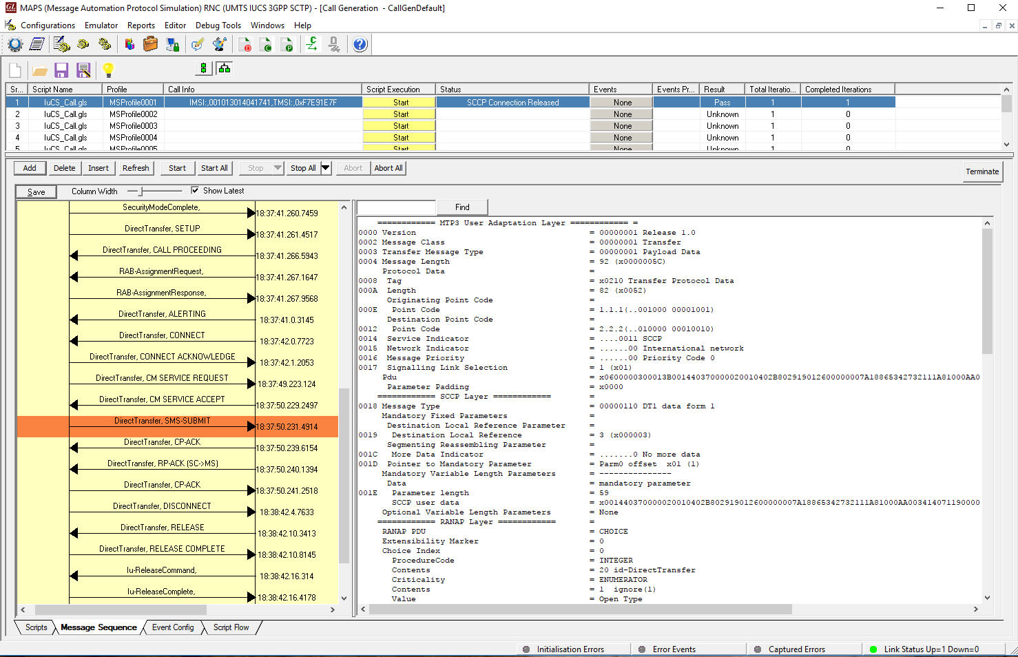
SMS over Voice Call Simulation at RNC
Handover Procedure Simulation
MAPS™ IuCS can be configured to simulate Handover (Relocation) procedure for a UE in CONNECTED state carrying both the control signaling and the user data. Both Source RNC and Target RNC are simulated within single testbed demonstrating Relocation procedure to move the connection between the Radio Access Network (RAN) and the Core Network (CN) for the source RNC to the RAN for the target RNC.
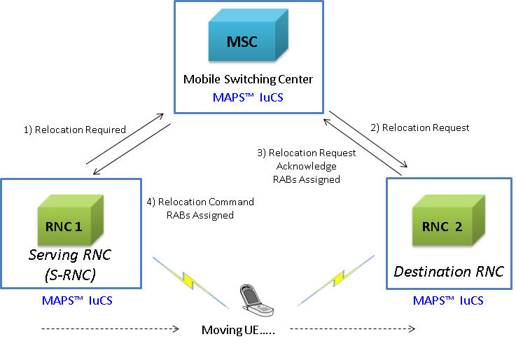
The following screenshot depicts end-to-end procedure simulation, you may observe the Relocate Required request messages sent from RNC1 to MSC and from MSC to RNC2.
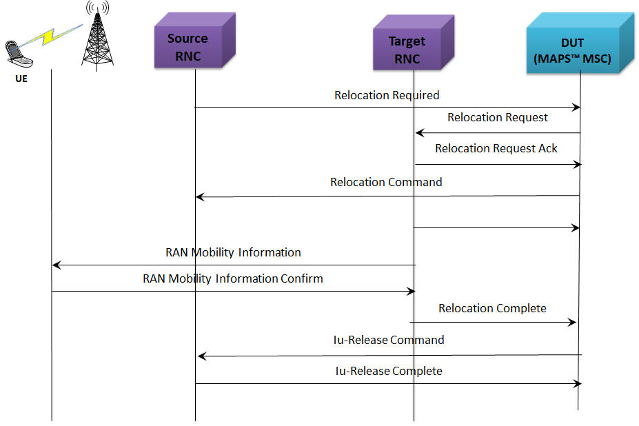
Handover (Relocation) Procedures
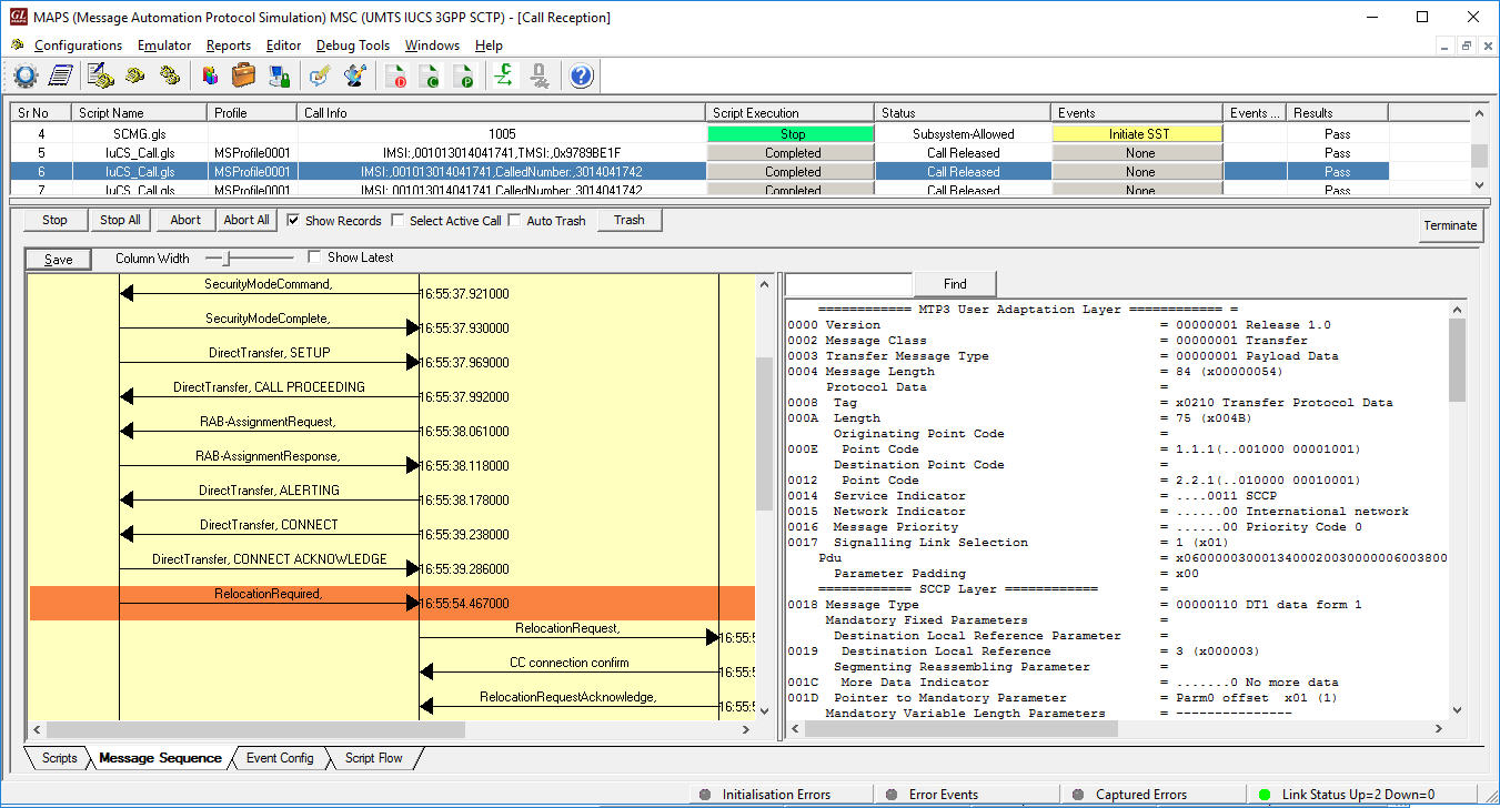
Relocation Procedure Simulation at MSC
Call Simulation over IuH IP
Call Generation option allows the user to simulate outgoing communications where an outgoing call is initiated by sending call control messages using proper scripts and profiles. MAPS™ application acts as either the Caller or resides at the network terminal acting as Callee.
In IuH interface, MAPS™ acts as either HNB to test HNBGW or HNBGW to test HNB and simulates the following call control procedures:
Supplementary Service Type Procedure:
Supplementary Service (USSD) is a communication protocol used by UMTS cellular telephones to communicate with the computers of mobile network operator. The following figure illustrates the Supplementary Service call flow between MAPS™- IuH and DUT.
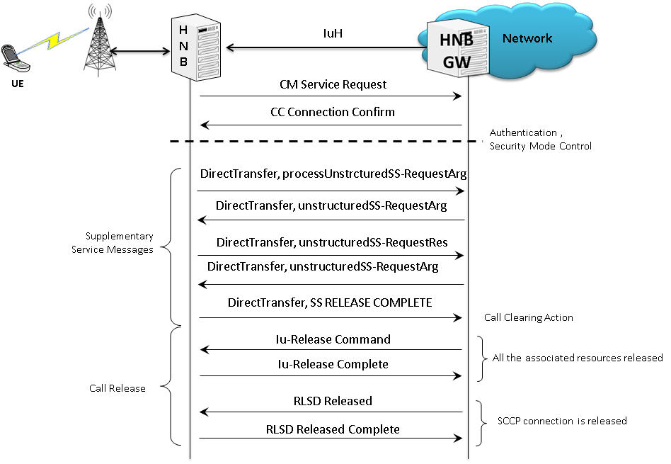
Typical Supplementary Service Call Flow over IuH IP
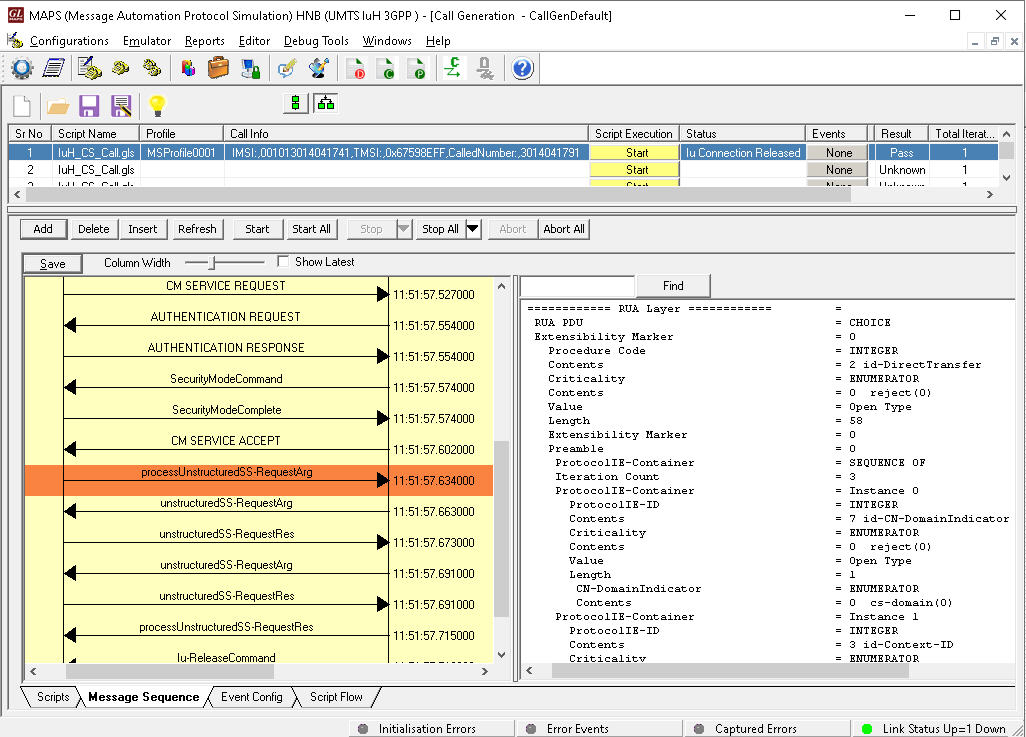
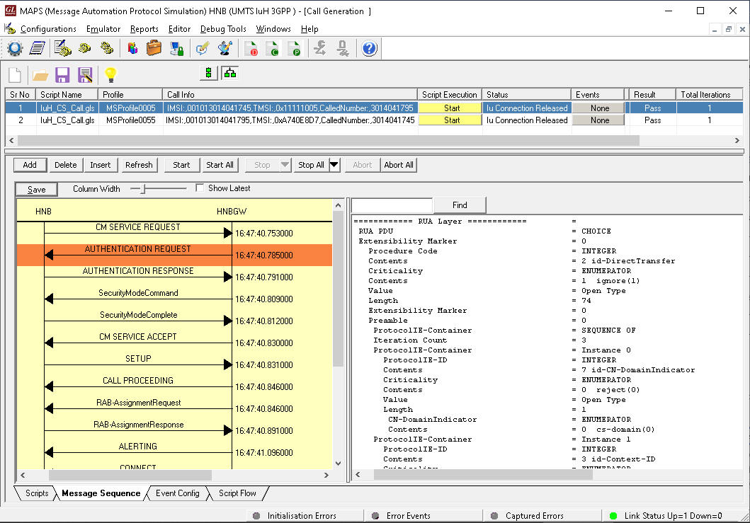
Supplementary Service Call Generation at HNB
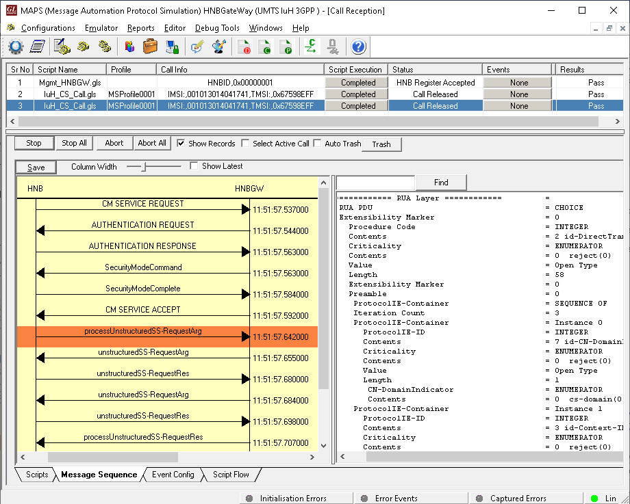
Supplementary Service Call Reception at HNBGW
Mobile to Mobile SMS Call Flow:
MAPS™ IuH supports mobile-to-mobile SMS procedure, sent or received from mobile phone-to-mobile phone.
The following figure illustrates the Mobile to Mobile SMS call flow between MAPS™- IuH and DUT.
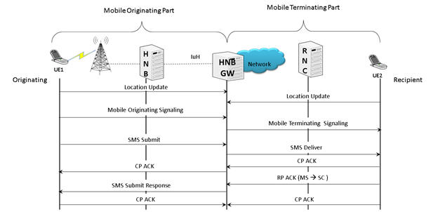
Mobile to Mobile SMS Call Procedure
Mobile to Mobile SMS Call Generation at HNB
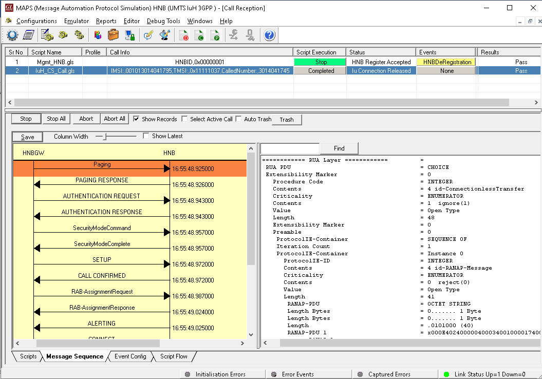
Mobile to Mobile SMS Call Reception at HNBGW
Bulk UE Simulation with CSV based Profiles
In real time scenario, there exists huge number of subscribers with unique UE parameters. MAPS™ supports bulk call generation to stress and load test the network with number of subscriber profiles. Each profile can have unique parameters to simulate different real-time scenarios. However, creating and maintaining massive number of XML based subscriber profiles with unique mobile identifiers such as IMSI, TMSI, MSISDN and traffic parameters is not feasible. Therefore, recent enhancements were introduced to MAPS™ UMTS IuCS and IuH test tools to include CSV subscriber profiles. CSV database system used within MAPS™ is a simple Excel® file that can dynamically generate up to 20,000 number of subscribers with unique identifiers (IMSI, TMSI, MSISDN) and other key parameters in sequential order.
MAPS™ also includes option to configure the ratio of SMS calls out of Total number of Calls. Considering 100% Total Calls, MAPS™ will generate SMS calls and MO Voice calls as per the defined ratio. For example, if the configured SMS call Ratio = 30% in Testbed, then during bulk call simulation, MAPS™ generates 30% SMS calls and remaining 70% of total calls generated will be MO Voice calls.
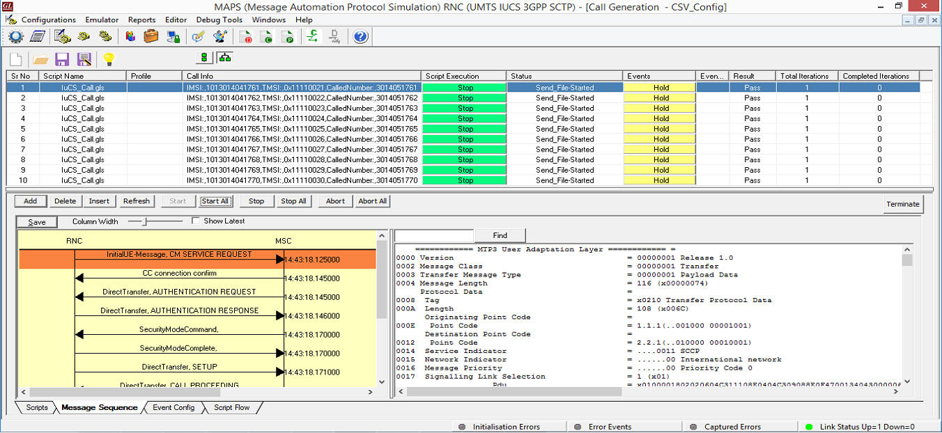
Bulk Call Generation with CSV based Subscriber Profiles
The call generation is based on the IMSI key parameter and call is received based on the Called Number key parameter. The Records are fetched from the CSV file for 2 different Key parameters, i.e., IMSI and CallingNumber. At MSC, 2 CSV files are saved in the working directory and is loaded in MAPS™, MS_Profiles_IMSI.csv file for key=IMSI, and MS_Profiles_CallingNumber.csv file for key=CallingNumber.
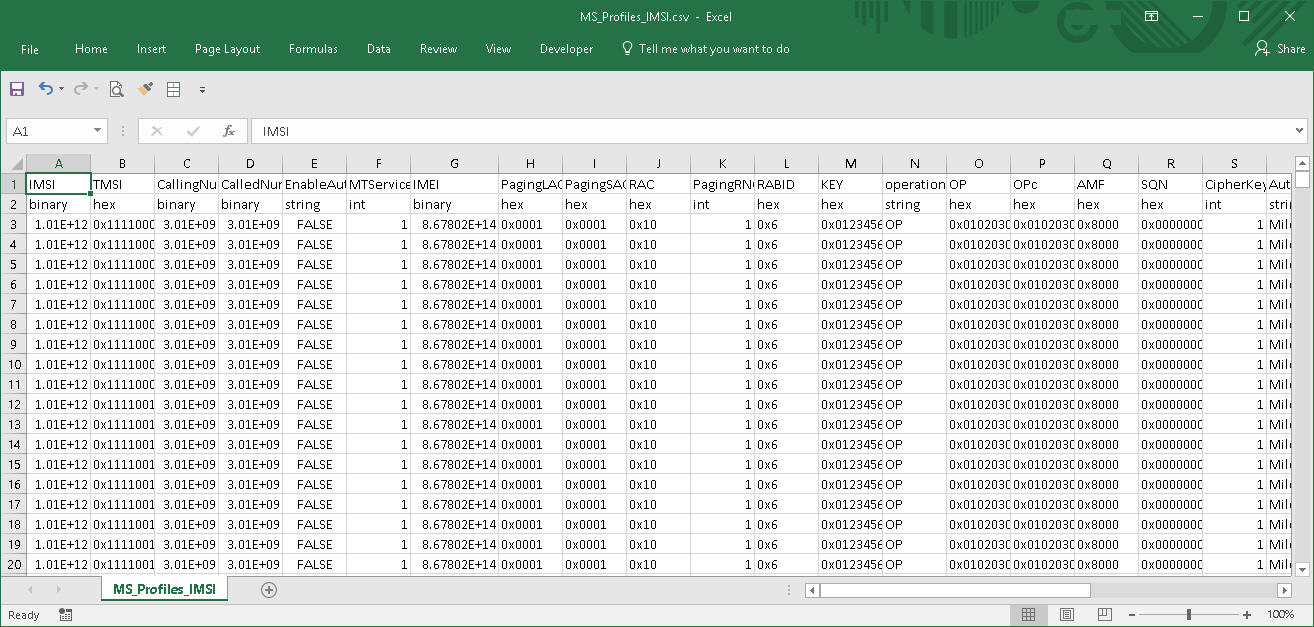
Sample MS_Profiles_IMSI.csv File
Resources
Please Note: The XX in the Item No. refers to the hardware platform, listed at the bottom of the Buyer's Guide, which the software will be running on. Therefore, XX can either be ETA or EEA (Octal/Quad Boards), PTA or PEA (tProbe Units), XUT or XUE (Dual PCIe Express) depending upon the hardware.
| Item No. | Item Description |
| MAPS™ UMTS IuCS IuH over IP | |
|---|---|
| PKS160 PKS102 PKS109 |
Message Automation & Protocol Simulation (MAPS™) - UMTS-IuCS Message Automation & Protocol Simulation (MAPS™) - UMTS-IuH RTP Soft Core for RTP Traffic Generation MAPS High-Density Call Generator for IP & Wireless Networks |
| MAPS™ UMTS IuCS ATM with LightSpeed1000™ | |
| LTS100 | Lightspeed1000™ - Dual OC-3/12 STM-1/4 PCIe Card |
| LTS105 | Lightspeed1000™ - Portable Dual OC-3/12 STM-1/4 USB Unit |
| LTS220 | OC-3 / STM-1 MAPS UMTS IuCS over ATM, requires LTS214 |
| LTS214 | OC-3 / STM-1 SSCOP Server |
| LTS217 | OC-3 / STM-1 AAL2 Traffic Core |
| LTS320 | OC-12 / STM-4 MAPS UMTS IuCS over ATM, requires LTS314 |
| LTS314 | OC-12 / STM-4 SSCOP Server |
| LTS317 | OC-12 / STM-4 AAL2 Traffic Core |
| Related Software | |
| PKS164 | MAPS™ UMTS IuPS interface |
| XX165 | T1 or E1 UMTS Protocol Analyzer |
| OLV165 | Offline UMTS Protocol Analyzer |
| LTS206 | OC-3 / STM-1 UMTS Protocol Analysis |
| LTS306 | OC-12 / STM-4 UMTS Protocol Analysis |