MAPS™ UMTS for IuPS Interface Emulator
Simulation of UMTS protocol for IuPS interface, a Gateway to the World Wide Web connecting RNC (Radio Network Controller) and the SGSN (Serving GPRS Support Node) elements handling data traffic.
Brochure Request a Quote
Background
UMTS, or Universal Mobile Telecommunications System is a 3rd generation mobile technology evolved from GSM technology. It uses W-CDMA (Wideband Code Division Multiple Access) as radio access. With increased spectral efficiency and high bandwidth, UMTS can support broadband data, voice and video. The underlying transport for UMTS in the core network can be Asynchronous Transfer Mode (ATM), or IP.
UMTS supports integrated services such as multimedia and global roaming to mobile users. In essence, UMTS IuPs interface is the Gateway to the World Wide Web. More precisely, IuPs, as shown in the figure, is the interface between the RNC (Radio Network Controller) and the SGSN (Serving GPRS Support Node).
SGSN manages mobile location whether within the carrier's network or roaming outside. Once a user turns on her mobile, a new IP address gets assigned and IP connectivity is available with quality of service (bit rate allocation) based on subscription, and tunnels are created for mobile flows to/from that mobile. These data tunnels carry encapsulated traffic such as http, ftp, email, etc. SMS may also be carried by the signaling plane to/from the mobile. IuPs emulation and analysis can be very important in the design, verification, and troubleshooting of a carrier's mobile data network.
The IP based UMTS network consists of the following components -
- Radio Network Controller (RNC)
- Mobile Switching Center (MSC)
- Serving GPRS Support Node (SGSN)
- Gateway GPRS Support Node (GGSN)
- NodeB
- Femto Home NodeB (Femto Cell) and Femto Home Node Gateway (HNB-GW)
Overview
GL's Message Automation & Protocol Simulation (MAPS™), is a protocol simulation and conformance test tool that supports a variety of protocols such as SIP, MEGACO, ISDN, SS7, GSM, LTE, and many other TDM, IP, and Wireless protocols. MAPS™ has been enhanced for testing UMTS IuPs interface. It can simulate RNC (Radio Network Controller), and 3G SGSN (3G Serving GPRS Support Node) by generating RANAP and DTAP signaling messages over SCTP as Transport layer in an IP network as defined by 3GPP standards.
The product also supports Mobile traffic core – GTP (ETH101) simulation for user-plane packet transmission and reception services between any two nodes in LTE and UMTS networks. Mobile Traffic Core – Gateway (ETH102) module allows simulation of Gateway Traffic to test media gateway telephony interfaces over IP. These modules also support generation and verification of data traffic such as Email, FTP, Web (HTTP), Video, and more.
The application gives the users the unlimited ability to edit messages and control scenarios (message sequence). “Message sequences” are generated through scripts. “Messages” are created using message templates.
The application is available as
- MAPS™ - IuPS (Item # PKS164)
In addition, GL also supports the following UMTS analyzers and simulators:
- MAPS™ UMTS IuCS & IuH Simulators (PKS160)
- T1 or E1 UMTS Protocol Analyzer (XX165)
- Offline UMTS Protocol Analyzer (OLV165)
- OC-3 / STM-1 UMTS Protocol Analysis (LTS206)
- OC-12 / STM-4 UMTS Protocol Analysis (LTS306)
GL has enhanced the MAPS™ protocol emulation tool to simulate multi-protocol and multi-interface offering a complete range of test solutions, covering the entire 2G, 3G, and 4G network.
By mimicking real-world customer behavior in lab environments, our solutions allow mobile operators and equipment manufacturers to verify their wireless networks before deployment. In other words, one can setup a virtual real-time network simulating all the network elements using “MAPS 3G Wireless Lab Suite”. The test suite supports simulation of IuH, IuCS, IuPS, C/D/Gr/Gd, and GnGp interfaces.
Main Features
- Setup a virtual real-time network simulating 3G-UMTS network element using ‘MAPS™ 3G Wireless Lab Suite’
- Supports PS network web browsing data traffic simulation along with generation of real-world traffic in the lab
- Simulates RNC, and SGSN network entities.
- Generates and supports all GPRS Mobility Management, Session Management, RANAP and DTAP messages.
- Supports GPRS Attach, Detach procedures, RUA, Paging, and Handover (Relocation) procedures.
- Ready scripts for handling SCTP, M3UA, and SCMG (SCCP Management) procedures
- Supports M3UA termination type as a signaling gateway process (SGP), an application server process (ASP), or an IP server process (IPSP).
- Supports Packet Traffic, Mobile Traffic, Gateway Traffic, External Gateway simulation with additional licenses
- Automation, Remote access, and Schedulers to run tests 24/7
Supported Protocol Standards
| IuPS Interface | |
| Supported Protocols | Specification Used |
|---|---|
| SCTP | RFC 4960 |
| SCCP | Q.713, CCITT (ITU-T) Blue Book |
| M3UA | RFC 3332 |
| RANAP | 3GPP TS 25.413 V9.1.0 |
| GMM / SM | 3GPP TS 24.008 V5.16.0 (2006-06) |
| SMS | 3GPP TS 03.40 V7.5.0 & 3GPP TS 04.11 V7.1.0 GSM 03.38 version 7.2.0 Release 1998 |
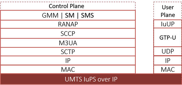
UMTS IuPS Protocol Stack
GPRS Attach Procedure
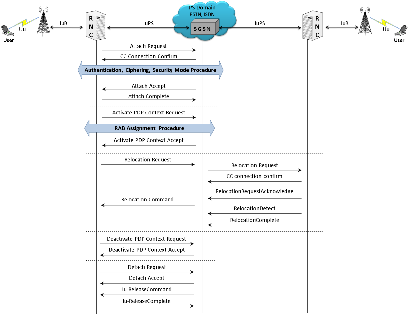
In IuPS interface, MAPS™ acts as either RNC to test SGSN (DUT) or SGSN to test RNC (DUT) simulating the Attach Request, Attach Accept, Attach Complete, Activate PDP Context Request, Activate PDP Context Accept, Deactivate PDP Contest Request, Deactivate PDP Contest Accept, Detach Request, Detach Accept, Iu-Release Command, Iu-Release Complete, and Routing Area Updating (RAU) procedures:
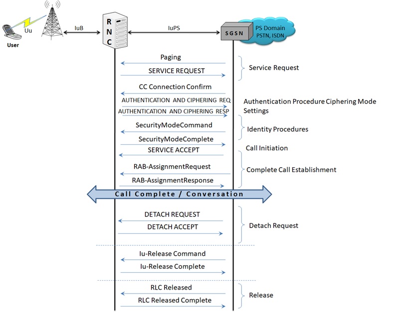
Typical Call Flow between the UMTS IuPS network entities
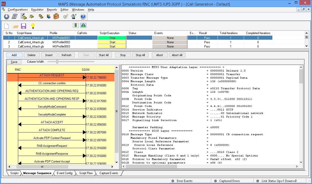
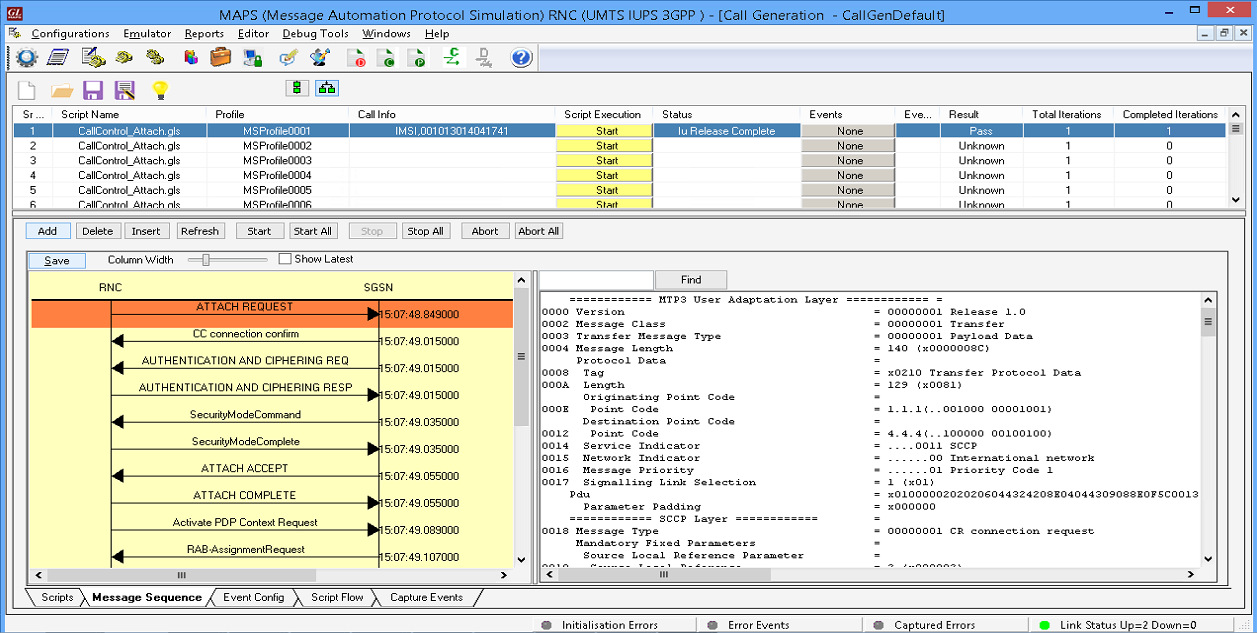
Attach Procedure at RNC Node over IuPS
(Call Generation)
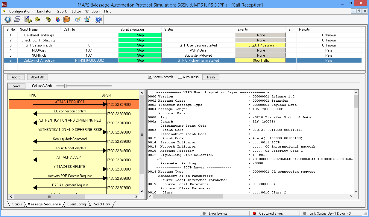
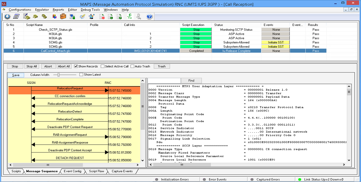
Attach procedure at SGSN Node over IuPS
(Call Reception)
Paging Procedure
Paging is used by the network (SGSN) to request RNC that the establishment of PS signaling connection or to prompt the mobile to re-attach if necessary, as a result of network failure. If the MS receives the paging indication in the same access network, as when it last sent user data or signaling information, the MS (RNC) shall send the SERVICE REQUEST procedure indicating service type "paging response".
The network (SGSN) shall initiate the paging procedure using P-TMSI when user data is pending to be sent to the MS (RNC). The network may page only MSs (RNC's) which are GMM-REGISTERED and identified by a local P-TMSI.
Typical Paging Call Flow
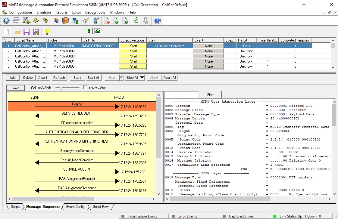 Mobile Terminating Call Generation
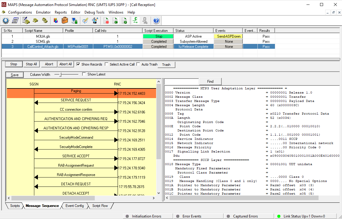
Mobile Terminating Call Reception
Relocation Procedure
This procedure is only performed for a UE in CONNECTED state where the Iur interface carries both the control signaling and the user data. The Serving SRNS Relocation procedure is used to move the connection between the RAN and the CN for the source SRNC to the RAN for the target RNC, from a "standing still position". In the procedure, the Iu links are relocated. If the target RNC is connected to the same SGSN as the source SRNC, an Intra-SGSN SRNS Relocation procedure is performed.
The procedure can be simulated in lab using MAPS™ IuPS configured as both Source RNC and Target RNC interconnected via SGSN.
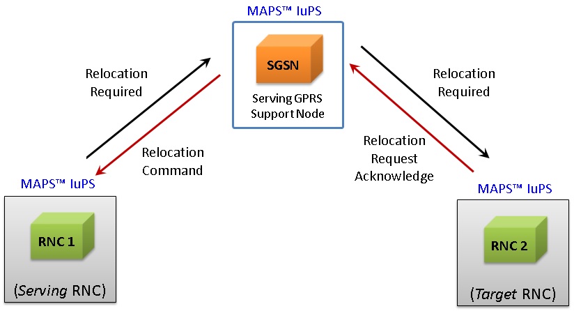
The typical Relocation Procedure between Serving RNC, SGSN, and Target RNC is as depicted in the call flow below:
RNC1 Call Generation
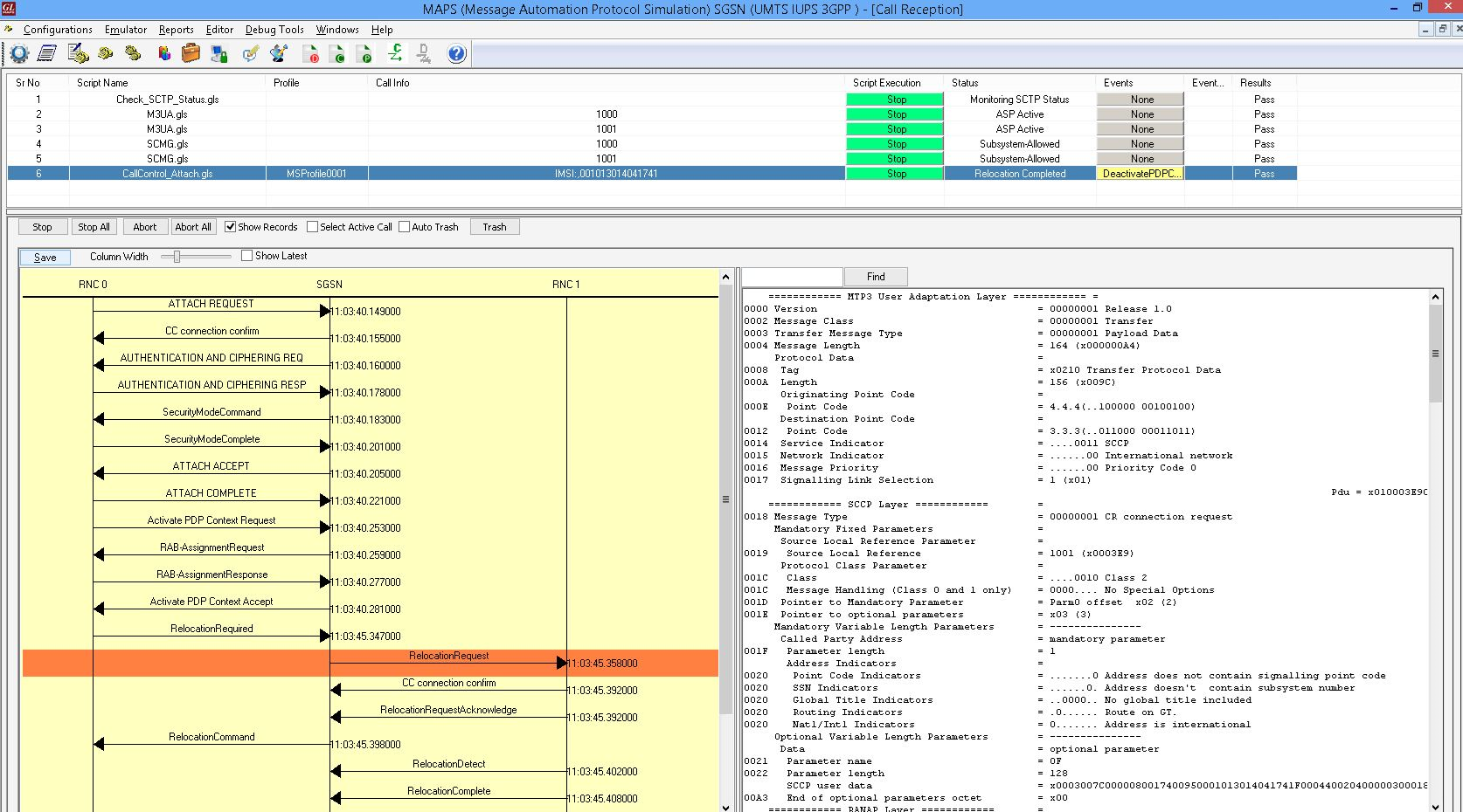
SGSN Call Reception
RNC2 Call Reception
Resources
Please Note: The XX in the Item No. refers to the hardware platform, listed at the bottom of the Buyer's Guide, which the software will be running on. Therefore, XX can either be ETA or EEA (Octal/Quad Boards), PTA or PEA (tProbe Units), XUT or XUE (Dual PCIe Express) depending upon the hardware.