MAPS™ GSM Abis Interface Emulator
GSM Abis Interface Emulation over IP and TDM
GSM Abis Brochure GSM Abis IP BrochureRequest a Demo / Quote

Background
GSM stands for Global System for Mobile Communication and is an open, digital cellular technology used for transmitting mobile voice and data services.
A GSM network is made up of multiple functional entities and interfaces that facilitate sending and receiving of signaling and traffic messages. It is a collection of transceivers, controllers, switches, routers, and registers.
The GSM network can be divided into following broad parts.
- The Mobile Station (MS)
- The Base Station Subsystem (BSS)
- The Network Switching Subsystem (NSS)
- The Operation Support Subsystem (OSS)
The MS and the BSS communicate across the Um interface, also known as the air interface or radio link. BTS and BSC will communicate across Abis interface and The BSS communicates with the Network Service Switching center across the A interface.
The Abis interface is used between the BTS and BSC. At this level, the radio resources at the lower portion of Layer 3 are changed from the RR to the Base Transceiver Station Management (BTSM). The BTS management layer is a relay function at the BTS to the BSC.
The RR protocols are responsible for the allocation and reallocation of traffic channels between the MS and the BTS. These services include controlling the initial access to the system, paging for MT calls, the handover of calls between cell sites, power control, and call termination. The RR protocols provide the procedures for the use, allocation, reallocation, and release of the GSM channels. The BSC still has some radio resource management in place for the frequency coordination, frequency allocation, and the management of the overall network layer for the Layer 2 interfaces.
Overview
GL’s MAPS™ is an advanced protocol simulator/tester for GSM Abis interface emulation over TDM and IP that can emulate BTSM messages and signaling specification as defined by 3GPP standards. The application supports testing network elements BTS and BSC, Error tracking, regression testing, conformance testing, load testing/call generation and generation of high volumes of GSM traffic. It is able to run pre-defined test scenarios against GSM Abis interface test objects in a controlled and deterministic manner.
MAPS™ emulator for GSM Abis protocol over TDM (with XX693 license) and over IP (with PKS134 license) supports powerful utilities like Message Editor, Script Editor and Profile Editor, which allow new scenarios to be created or existing scenarios to be modified using BTSM messages and parameters.
MAPS™ GSM Abis over TDM supports TRAU traffic with additional licenses. The TRAU Traffic commands includes Transmit TRAU DTMF Digits (Send TRAU File, Send TRAU Tones), Receive Actions (Monitor TRAU Digits, Rx TRAU File, Monitor TRAU Tones), and Stop Traffic Actions.
GL has enhanced the MAPS™ protocol emulation tool to emulate multi-protocol and multi-interface offering a complete range of test solutions, covering the entire 2G, 3G, and 4G network.
By mimicking real-world customer behavior in lab environments, our solutions allow mobile operators and equipment manufacturers to verify their wireless networks before deployment. In other words, one can setup a virtual real-time network emulating all the network elements using “MAPS™ 2G Wireless Lab Suite”. The test suite supports emulation of GSM Abis, GSM A, C/D/E, Gb, and GnGp interfaces.
MAPS™ GSM Abis over IP supports CS Domain RTP traffic with additional PKS102 licenses. Supported RTP traffic types include – Auto Traffic Tx Rx File, Tones, Digits, FAX, User-defined traffic, and IVR.
With the purchase of RTP Core license (PKS102), MAPS™ GSM Abis supports transmission and detection of CS Domain RTP traffic such as, digits, voice file, single tone, dual tones, IVR, FAX*, and Video*. With regular RTP traffic, the maximum Simultaneous Calls up to 2500, and Calls per Second up to 250 is achievable. Almost all industry standard voice codec supported.
** Some of these traffic types requires additional licenses – contact GL for more information
GL also provides an independent GUI based GSM protocol analyzer for TDM interfaces (optional application – XX150) and PacketScan™ for IP interfaces (optional application – PKV100) for online capture and decode of the signaling in real-time both during tests and as a stand-alone tracer for live systems.
Possible applications include:
- Setup a virtual real-time network emulating 2G-GSM GPRS network elements using ‘MAPS™ 2G Wireless Lab Suite’
- Multi-protocol, Multi-interface emulation
- Provides fault insertion, and erroneous call flows testing capability.
- Performance testing, Load Testing, Function al testing, Regression testing and Conformance testing of network elements.
- Ready scripts makes testing procedure simpler, less time consuming and hence time to market products.
- Test response of network against protocol message modification, or corruption
- Inter-operability testing of networks
- Wrap-around testing (WAT)
- SMS Testing from within the Wireless Infrastructure using MAPS™
Supported Protocols Standards
 |
|
Location Updating Call Procedure
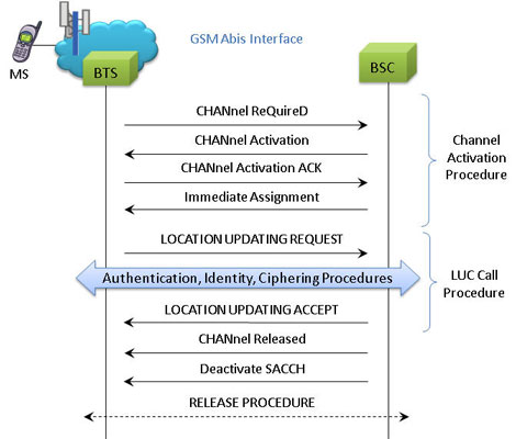
LUC Procedure
LUC Generation and Reception
The MAPS™ GSM Abis is considered to act as Base Transceiver Station (BTS) and initiating the call flow by sending Location Updating Request to the BSC (Base Station Controller). The DUT (BSC) on receipt of a LOCATION UPDATING REQUEST message initiates authentication process by sending AUTHENTICATION REQUEST. Also, simulates the complete call flow as in typical Location Updating Call (LUC) procedure.
LUC Call Generation
LUC Call Reception
Mobile Originating Call Procedure
MOC Procedure
MOC Generation and Reception
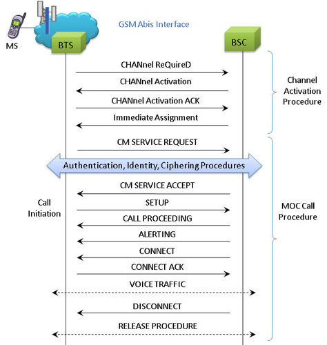
MAPS™ GSM Abis interface includes inbuilt scripts (*.gls) that allows itself to act as BTS initiating Mobile Originating Call and test BSC in the network. The MAPS™ GSM ABis sends Channel Required message to the BSC in the network. The DUT (BSC) on receipt of a Channel Required message, sends a Channel activation and channel activation acknowledgement message in response. Also, emulates the complete call flow as in typical Mobile Originating Call (MOC) procedure.
MOC Call Generation
MOC Call Reception
Mobile Terminating Call Procedure
MTC Procedure
MTC Generation and Reception
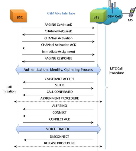
MAPS™ GSM Abis is located at the network as Base Station Controller (BSC) initiating the call flow by sending the Paging message to the Mobile Station (BTS). The DUT (BTS) on receipt of a Paging message, sends a Paging Response message back to BSC. This can be observed in Call Reception window at BSC node. Also, emulate the complete call flow as in Mobile Terminating Call (MTC) call flow.
MTC Call Generation
MTC Procedure Paging Response
MTC Call Reception
Resources
Note: PCs which include GL hardware/software require Intel or AMD processors for compliance.
Please Note: The XX in the Item No. refers to the hardware platform, listed at the bottom of the Buyer's Guide, which the software will be running on. Therefore, XX can either be ETA or EEA (Octal/Quad Boards), PTA or PEA (tProbe Units), XUT or XUE (Dual PCIe Express) depending upon the hardware.