Echo Measurement Utility (EMU)
GL's Automated Data Quality Testing
Latest Software
- Echo Measurement Utility (EMU) Software Ver 9.12.13
Brochures
Overview
GL's Echo Measurement Utility (EMU) software is an offline adjunct analysis application (under control of VQuad™) that compares the source and received files to determine echoes and delay of echoes. EMU software assesses sidetone, line, and acoustic echo and the corresponding delays.
Echo Measurement Utility Software (EMU) measures Echo Path Delay (EPD) and Echo Return Loss (ERL) of voice calls. Echo can be as simple as sidetone, or more complex such as line, and acoustic echo. The EMU when combined with GL’s VQuad™,T1 E1 Analyzers, MAPS™ Emulators, or Voiceband Analyzer, additional voice quality metrics such as round-trip delay (RTD), voice quality, and noise can also be measured.
To provide a comprehensive assessment of voice quality irrespective of network type, GL has combined various tools together into one platform consisting of VQuad™, Dual UTA HD, USB T1 E1, and WEBViewer™. This platform provides the ability to make VoIP, TDM, and Mobile calls from any fixed or mobile location. All interface flexibility is provided (2Wire, 4Wire, VoIP, TDM, and Mobile) within the Dual UTA HD and USB T1 E1 Analyzers. In addition, VQuad™ provides algorithms for signaling, voice transmission, and voice quality assessment. WEBViewer™ provides the central point where voice metrics are stored and displayed through a WEB interface.
Depiction of 2-Wire Echo Measurement
Main Features
- Echo, delay, and voice quality analysis of voice calls in VoIP, TDM, 2Wire, 4Wire, and Mobile networks.
- Measures EPD in msec and ERL in dB.
- Compares source and received files to detect maximum of 4 echoes (maximum of four instances).
- Ability to automate the entire test process using VQuad™ scripting; including sending the results to the central database for access via GL's WebViewer™.
- EMU uses EMU Client software to automatically detect the incoming degraded voice files and send the measurements to database after analysis.
- Detailed offline analysis.
- Detect Acoustic/Line (Hybrid) echoes and evaluate intermittent echoes
- Supports Auto and Manual methods of operation.
- Graphically displays source signal, received signal, error signal, and adaptive filter coefficients.
- Allows zoom-in on each graph, exporting snapshots of these graphs to files for later analysis.
- Calculates adaptive filter coefficients and echo characteristics for the error signal.
- Speaker option to play the audio files (intrusive and non-intrusive)
- Option to zoom-in on any particular echo to investigate further
Line (Hybrid) Echo Analysis
The following outlines the Line (Hybrid) Echo and Acoustic Echo scenarios where the EMU is used with VQuad™ and/or MAPS™ Emulators tools to send and receive voice files for the purpose of Echo measurement.
Two wire - Two wire Hybrid Echo Measurement
As depicted in the above picture, a call is placed from one port of RJ11 to other port of RJ11 through an outside Central Office. Due to hybrid circuitry in the overall path, echo exists as side-tone and line (hybrid) echo.
Two wire - Mobile Hybrid Echo Measurement
Call is placed from one port of RJ11 to a mobile where the connection path is shown above. Echo cancellers exist in the two-wire to mobile path between central office to base station.
- Intrusive file sent from Port of RJ11 (2-wire) to mobile - The one echo, which can be seen in this setup, is the side-tone as shown at 2-wire connection.
- Intrusive file sent from mobile to Port of RJ11 (2-wire) - There will be no side tone with mobile connection, but there could be line (hybrid) echo depending on the EC performance / existence.

Two wire (direct to gateway) - VoIP Hybrid Echo Measurement
Call is placed from one port of RJ11 to VoIP phone through the gateway and Ethernet network. Based on the configuration of echo canceller (EC) in the gateway, which can be enabled or disabled, echo exists at the VoIP phone. At the PC / Dual UTA HD there will be side-tone.
- Intrusive file sent from Port of RJ11 (2-wire) to VoIP phone - The one echo, which can be seen in this setup with Echo Canceller setting enabled, is the side-tone as shown at 2-wire connection.
Two wire (through T1 E1 switch) - VoIP Hybrid Echo Measurement
Call is placed from one port of RJ11 to VoIP phone through the Class 5 T1 E1 Switch, Gateway and Ethernet network.
Echo cancellers exist in the two-wire to VoIP phone path as part of the gateway. The one echo, which can be seen in this setup, is the side-tone at the PC / Dual UTA HD. The VoIP phone may experience echo depending on the EC performance.
Two wire (through T1 E1 switch) - Ethernet Hybrid Echo Measurement
Call is placed from one port of RJ11 to Ethernet interface of VQuad™ software through the Class 5 T1 E1 Switch, Gateway and Ethernet network. Echo cancellers exist in the two-wire to Ethernet interface of VQuad™ software path between Class 5 T1 E1 Switch. The one echo, which can be seen in this setup, is the side-tone. On the VoIP side, there may be echo based on the performance of the EC.
Two wire (direct to gateway) - Ethernet Hybrid Echo Measurement
Call is placed from one port of RJ11 to Ethernet interface of VQuad™ software through the gateway and Ethernet network. An echo canceller exists in the overall path in Ethernet interface and also in gateway based on the configuration. Side-tone exists at the 2Wire and may exist at the VoIP connection depending on the performance of the EC.
Mobile phone to Mobile phone Hybrid Echo Measurement
Call is placed from near-end mobile phone (4-wire analog) to far-end mobile phone (4-wire analog). Generally, there are no ECs in mobile to mobile connections. There is no side-tone as mobile is connected in headset mode.
Mobile phone to VoIP Hybrid Echo Measurement
Call is placed from near-end mobile phone (4-wire analog) to Ethernet interface of the other port via VoIP phone or vice versa.
- Intrusive file sent from Mobile to VoIP phone or VQuad™ (Ethernet Interface) - Echo cancellers exist in the mobile network. There is no side-tone as mobile is connected in headset mode.
- Intrusive file sent from VoIP phone or VQuad™ (Ethernet Interface) to Mobile - Echo cancellers exist in overall path. The one echo, which can be seen in this setup, is the side-tone at the VoIP phone.

Ethernet - IP PBX - 2Wire Hybrid Echo Measurement
Call is placed from one port of RJ11 to Ethernet interface of VQuad™ software through IP PBX exchange, Ethernet network or vice-versa.
VoIP phone - IP PBX - 2Wire Hybrid Echo Measurement
Call is placed from one port of RJ11 to VoIP phone through IP PBX exchange, Ethernet network or vice-versa.
- Intrusive file sent from VoIP phone to RJ11 (2-wire) port - Echo cancellers exist in overall path. The one echo, which can be seen in this setup, is the side-tone as shown across the VoIP phone.
Acoustic Echo Analysis

Acoustic Echo Measurement in VoIP
Referring to the above picture, call is being generated from RTP ToolBox™ (or VQuad™ VoIP SIP Soft-phone) of computer 1 to computer 2. The configuration at computer 2 is such that the file received at computer 2 is played to the speaker and the audio is sent back to source using the microphone. The intrusive and received files at computer 1 are compared for echo measurement. The path of acoustic echo is depicted in dotted lines, which is the leak between the speaker and mic of computer 2.
EMU - ERL vs Delay Measurement
The GUI displays "ERL vs Delay" plot where the echo is indicated with a circle on top of each echo peak. The table in the "Echo Characteristics" panel is updated with a maximum of 4 echoes. Each echo result includes the ERL in dB and delay in msec.
Echo Measurement Utility (EMU) ERL Vs Delay Analysis
Measurement Parameters and Operating modes
The following parameters can be customized to control the EMU input and output –
- Filter Coefficients Length
- Step Size
- Double talk Detector Threshold
- Double talk Detector Hangover Time
- Echo power window length
- Single talk Threshold
- ERL threshold
- Minimum Single talk length
- Maximum Single talk length
- Sampling rate
Screen shot of EMU parameter settings
There are two methods in EMU to measure the echo characteristics:
- Auto Method - the input files are analyzed and the echo characteristics are given as blocks (Blocks are divided based on time duration of input files and parameter settings).
- Manual Method – after analyzing the input files, the users have to manually select a region of Input / Output stereo signal plot to obtain the echo characteristics results.
Screen shot of EMU Auto Method Echo Characteristics Measurements
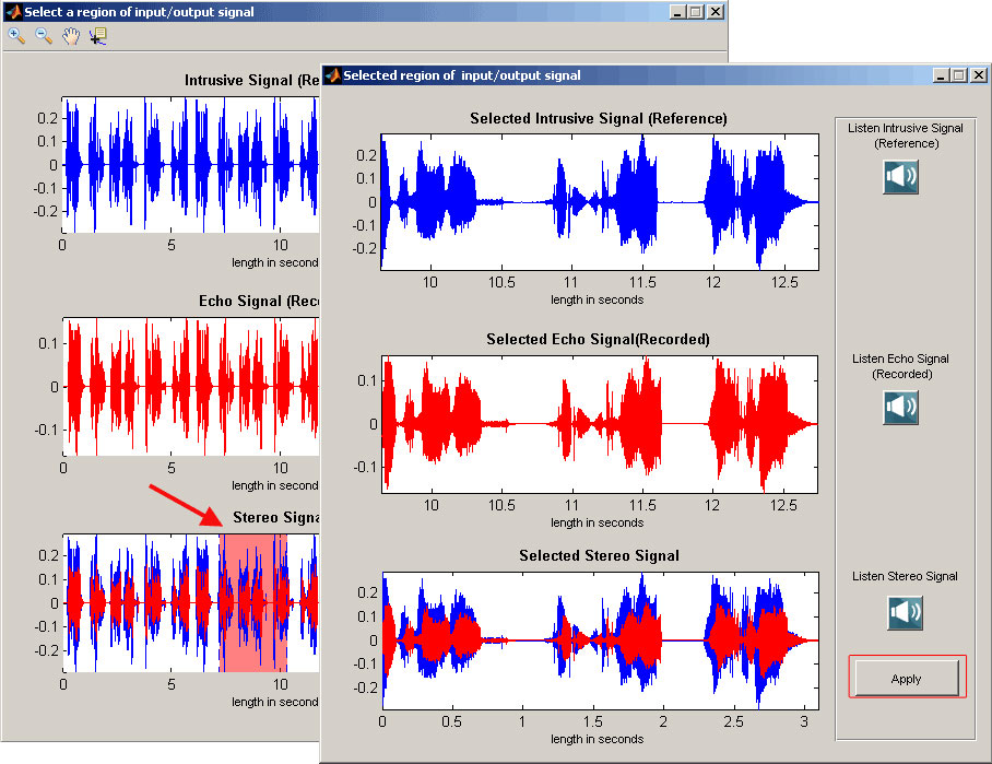
Screen shot of EMU Manual Method Echo Characteristics Measurements
Detail Analysis Option
The "Detailed Analysis" GUI consists of intrusive and received signal displays (in dBm format), error signal display (in seconds), adaptive filter coefficients display and the table of echo characteristics. Speaker option in detailed analysis allows playing audio files and to gauge overall performance of the echo diagnostics. Cursor selection option calculates the mean filter coefficients for the particular point in the error signal.
Screenshots of Detail Analysis of Adaptive Filter coefficients and echo signal
Result Sheet
The Operator information option is used to print the result in spread sheet. The generated "Result" spread sheet includes operator information, file information, echo characteristics, and snapshots of all the signal graphs.
Result Sheet
Screen Shot of ERL_VS_Delay sheet
Screen Shot of Error and Filter Coefficients sheet
Screen Shot of Intrusive Received sheet
EMU Client
The VQuad™ along with the File Monitor Utility forms a system, which generates and terminates a variety of connections including 2-wire Analog (FXO), 4-wire Analog, T1 E1, and SIP VoIP. The recorded files on this system will be automatically transferred to the EMU system for analysis.
The EMU Client (running on same system as EMU) monitors the incoming degraded voice files and informs the EMU to analyze these files based on parameters associated with the degraded voice filename. These parameters indicate the Intrusive Reference Voice File to be used, Line or Acoustic Echo mode, Time or Frequency Domain. The results are sent to Central Database system. With this, the remote users can access the EMU results using WebViewer™.
EMU Client monitoring degraded voice files
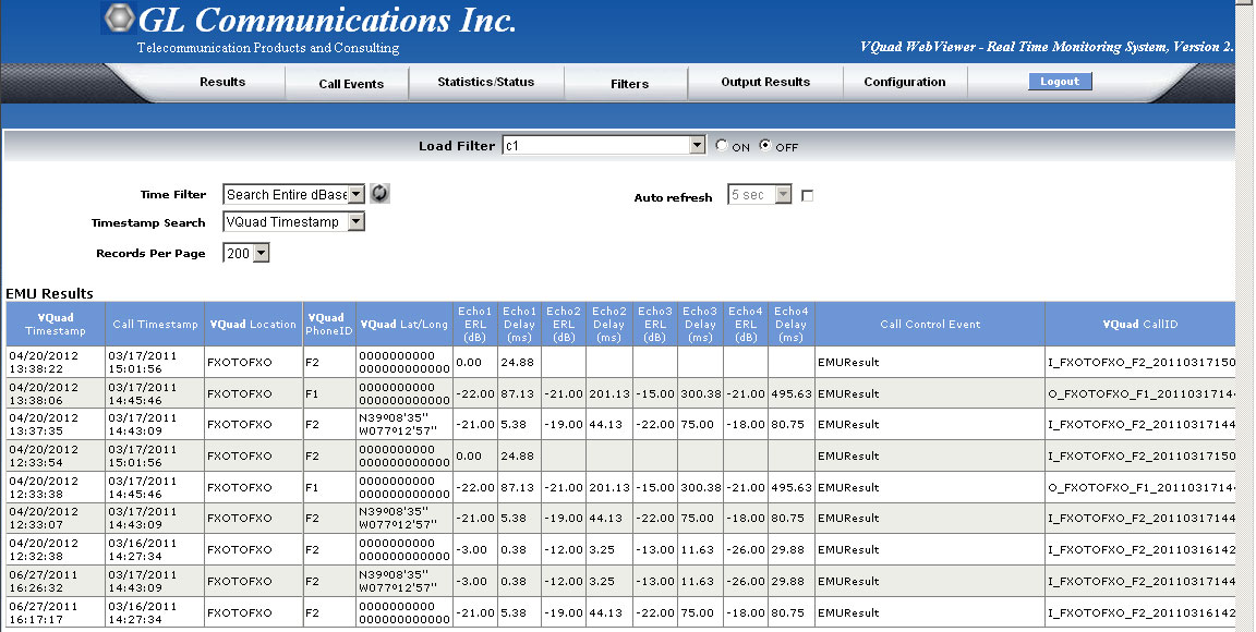
WebViewer™ displaying EMU results
Echo Measurement Utility (EMU) with GL Tools
The EMU requires only two files to function – the 'sent' file and simultaneously recorded 'received' file. Any tool that achieves this can be used with the EMU.
GL provides various emulation and capture tools that are compatible with the EMU:
- For VoIP - VQuad™ or MAPS™ SIP
- For Mobile Phones - VQuad™ with Dual UTA HD or MAPS™ Emulators
- For TDM - VQuad™ with USB T1 E1 unit, or Any T1 E1 Analyzer (Octal/Quad T1 E1, tProbe™ T1 E1 unit, tScan16™, Dual PCIe T1 E1 Card)
- For 2-Wire - VQuad™ with Dual UTA HD, tProbe™ FXO FXS
- For 4-Wire - VQuad™ with Dual UTA HD, or Any T1 E1 Analyzer (Octal/Quad T1 E1, tProbe™ T1 E1 unit, tScan16™, Dual PCIe T1 E1 Card)
EMU can be used effectively with VQuad™ software and different hardware to support nearly any network interface. The figure below depicts EMU working with VQuad™withDual UTA HD intrusive tool. VQuad™ software along with the Dual UTA HD hardware supports transmitting and receiving files across the following interfaces: RJ11 2-wire analog, 3.5 mm jack for mobile headset connection, Handset phones and balanced I/O for VoIP soft phones.
In addition, VQuad™ provides the capability to remotely control the EMU through scripting, thus, automating the entire testing process including sending results to the central database for access via GL’s WebViewer™.
For more details, visit Dual UTA HD and VQuad™ webpage.
VQuad™ with Dual UTA HD (Item # VQT251)
EMU can be used effectively with VQuad™ software and different hardware to support nearly any network interface. The figure below depicts EMU working with VQuad™with Dual UTA HD intrusive tool. VQuad™ software along with the Dual UTA HD hardware supports transmitting and receiving files across the following interfaces: RJ11 2-wire analog, 3.5 mm jack for mobile headset connection, Handset phones and balanced I/O for VoIP soft phones.
In addition, VQuad™ provides the capability to remotely control the EMU through scripting, thus, automating the entire testing process including sending results to the central database for access via GL’s WebViewer™.
For more details, visit Dual UTA HD and VQuad™ webpage.
EMU with GL’s Intrusive VQuad™ Tool
MAPS™ SIP or VQuad™ with VoIP option
GL’s MAPS™ Emulator or VQuad™ with VoIP option can be used with EMU to assess line or acoustic echo.
Acoustic Echo Measurement in VoIP
T1 E1 Analysis or VQuad™ with T1 E1 Option (Item # VQT015)
GL’s T1 E1 Analysis application (requires hardware) is used with EMU to detect possible echoes through a T1 E1 channel. Through T1 E1 WCS scripting or VQuad™ with T1 E1 option it is possible to automate the entire testing process including sending and receiving files. The intrusive files and the received files are fed as input to EMU for further analysis.
EMU with GL’s Intrusive T1 E1 Analysis Application
Resources
Please Note: The XX in the Item No. refers to the hardware platform, listed at the bottom of the Buyer's Guide, which the software will be running on. Therefore, XX can either be ETA or EEA (Octal/Quad Boards), PTA or PEA (tProbe Units), XUT or XUE (Dual PCIe Express) depending upon the hardware.