DTMF/MF Transmit & Capture Digits/Tones
Real-time Multi-Channel Audio Bridge application is included with T1 E1 Basic Software
Capture Dialed Digits:
The Capture Dialed Digits application provides the capability to capture and display DTMF and MF digits (along with MFR2-forward and MFR2-backward) digits and User-Defined tones as they are received on one or several time slots. Multiple Capture application boxes may be opened, each with different operating modes and options. The two different basic modes of operation are: Manual and Scan for Off hook Modes.
In Manual mode, the capture operation simply stays on the selected time slot, displaying the digits received, where as in ‘Scan for Off hook Mode', the scanning of successive time slots takes place and a detection of a onhook to offhook transition at a time slot would mark the beginning of the capture activity. There are different options with which the capture application can be performed.
- The ‘Digits only’ will capture only the digits on a time slot
- The ‘All Activity’ will capture digits and unrecognized bursts
- The ‘Detailed Analysis’ will record precise time measurement of each digit or burst, component frequencies and power
The application allows controlling the capture process as follows:
- Select various encoding standards such as DTMF, MF, User-defined tones, Ring/Dial/busy tones, MFR2-forward, and MFR2-backward for detection
- Set thresholds for power, duration, and signal-to-noise ratio when detecting energy bursts and comparing tone composition to various standards
- The burst power threshold value acts as a separating line between recognized digits and bursts for invalid digits/unrecognized data
- The interburst length threshold which is the minimum duration for an interburst so that the preceding and following bursts will be treated separately
- The signal to noise ratio parameter allows the digit detector to distinguish between bona fide digits and noise or voice bursts which happen to have significant power in one of the DTMF/MF digit frequency ranges
- Change OffHook and OnHook definitions
- Define frequency component for miscellaneous tones
- Captured digits can be saved to .txt file using logging option
Now, DTMF/MF/MFC-R2 Detector & Generator Software (xx022) is available as a part of basic applications in T1 E1 Analyzer.
Screenshots of Capture Dialed Digits:

Enabling various standards tab
Parameters definitions tab
User-defined tone components tab
Signaling definitions tab
Logging tab
Transmit Dialing Digits:
The Transmit Dialing Digits application provides the capability to transmit DTMF, MF, MFR2-forward, MFR2-backward, transmitting signal data from files, and directly from the T1 E1 VF input, applying signaling bits control, and performing other functions related to call establishment, progress, and termination. The application provides the following features -
The Transmit Dialing Digits applications' interface includes options to set up/ place a call, and control tone frequencies, OnHook and OffHook definitions, and other parameters related to the call.
The Dial tab features the following:
- A call script window where the user visualizes the various digits and transmit events, receive events that the user clicks for a call establishment
- A Keypad that changes the digits display in accordance with various standards DTMF, MF, MFR2-f and MFR2-b
- Options to set the Digit on-time/off-time, and digit power
- Options to save call scripts and retrieve for further testing
- Transmit event options include - on-hook, off-hook, wink, pause for a specified duration, route data from a file as a part of conversion, and insert T1 E1 VF input onto the selected time slot options
- Receive events such as to wait for onhook or offhook signaling pattern, and wait for a wink signal (onhook to offhook to onhook) from the other card as a part of call establishment (two cards talking to each other)
- Both Tx and Rx events can be controlled using timer
Other parameters controlled during digit transmissions:
- Vary the frequencies along with power twists for digits in the corresponding encoding standard in each tab
- With the help of sliders, the digit frequencies of each standard could be varied up to 5% of the nominal frequencies
- Power twists common to all digit frequencies could be varied for each standard
Now, DTMF/MF/MFC-R2 Detector & Generat or Software (xx022) is available as a part of basic applications in T1 E1 Analyzer.
Screenshots of Transmit Dialing Digits:

DTMF Parameters tab
Set Up tab - Setting up the call establishment parameters
Call Script Window with options tab
MF parameters tab
MFR2-f parameters tab

MFR2-b parameters tab
Sample script for 'Tx dialing digits':
An instance of a two way communication (two way conversation) between the cards could be explained by a call script built upon transmit events, receive events and the keypad (digits). The two way conversation is exhibited by a transmission at one end (Transmit card) and the complementary reception and response from the other end (receive card). Both the cards must be at the same time slot.
Shown below is a sample script which may be used to originate a call(transmit card) at a particular time slot when the GL Analysis card is connected to a T1 wink start (R1) system.
Tx Sig Bits 0000
Pause 100
Rx Await Sig Bits 0000:t/o=10000
Pause 100
Tx Sig Bits 1111
Rx Await Sig Bits 0000:t/o=10000
Pause 100
Rx Await Sig Bits 1111:t/o=10000
Pause 100
Rx Await Sig Bits 0000:t/o=10000
Pause 100
Tx DTMF-1: on=50,off=50,p=-10.0,p1=-13.0,f1=697,p2=-13.0,f2=1209
Pause 100
Tx DTMF-2: on=50,off=50,p=-10.0,p1=-13.0,f1=697,p2=-13.0,f2=1336
Pause 100
Tx DTMF-3: on=50,off=50,p=-10.0,p1=-13.0,f1=697,p2=-13.0,f2=1477
Pause 100
Tx DTMF-4: on=50,off=50,p=-10.0,p1=-13.0,f1=770,p2=-13.0,f2=1209
Pause 100
Tx DTMF-5: on=50,off=50,p=-10.0,p1=-13.0,f1=770,p2=-13.0,f2=1336
Pause 100
Tx DTMF-6: on=50,off=50,p=-10.0,p1=-13.0,f1=770,p2=-13.0,f2=1477
Pause 100
Tx DTMF-7: on=50,off=50,p=-10.0,p1=-13.0,f1=852,p2=-13.0,f2=1209
Rx Await Sig Bits 1111:t/o=10000
Tx File'C:\Program Files\Gl Communications Inc\Dual Pci Ultra T1 Analyzer\Mu-Law Samples\Vijay.pcm':10000
Tx Sig Bits 0000
Pause 100
In this script, receiver waiting for signaling bits 0000 to make sure both ends are in Onhook state follows a transmission of signaling bits 0000. Transmit signaling bits 1111 to originate the call from near end. A wink signal (0000 to 1111 to 0000) is awaited, which has to be sent from the far end before dialing the digits from the transmit card. These are keyed in from the transmit events. Once it receives the wink signal of duration between 10ms and 1000ms in the above script (during a waiting period of 10000ms), near end proceeds to dial the digits of a selected standard (DTMF in this case). As a part of the conversation with the other card, initially near end waits for the second card (far end) to transmit the signaling bits 1111, after which it transmits a voice input for a specified amount of time from the GL's card. After the conversation, as a part of call termination, a signaling bit pattern 0000 could be transmitted from near end with the assumption that the near end is terminating the call.
Shown below is a sample script which may be used to answer a call when the GL Analysis card is connected to a T1 wink start (R1) system.
Tx Sig Bits 0000
Pause 100
Rx Await Sig Bits 1111:t/o=10000
Tx Sig Bits 0000
Pause 100
Tx Sig Bits 1111
Pause 100
Tx Sig Bits 0000
Pause 1000
Tx Sig Bits 1111
Tx File'C:\Program Files\Gl Communications Inc\Dual Pci Ultra T1 Analyzer\Mu-Law Samples\Vijay.pcm':10000
Pause 100
Tx Sig Bits 0000
Pause 100
The near end card complements the transmit card and acts as a part of the conversation process for receiving from and responding to the transmit card(far end). The near end card initially transmits signaling bits 0000 and waits for other end to transmit 1111. After receiving 1111, near end sends the wink signal (0000 to 1111 to 0000) to the transmit card for which the latter had been awaiting, for a specified interval. Also, it transmits signaling bits 1111 to the far end card, since the latter has been waiting for the signaling bits 1111. The near end card transmits a VF input from the GL's card for a specified duration (10000msec). Towards the call termination (from near end), near end transmits the signaling bits 0000 to the other card, which will terminate the call by sending 0000 to near end.
Basic Call Emulation :

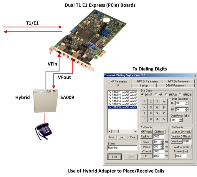
For more information about the applications of 2/4 wire hybrid.
Originating and Receiving Actual Calls
The Transmit Dialing Digits application can also allow the T1 E1 Analyzer to be used as a very basic call Emulator. Using a simple,
easy to create script, this application can manually place (originate) actual phone calls to a switch. This works on T1 systems using
R1 (wink) protocol, and on E1 systems using MFC-R2 protocol. For T1 systems using R1, this application can also receive (answer)
simple calls. Inserting the 'Tx VFIn' command into the script allows the use of an optional
telephone handset to actually talk and listen on the established
call. (Optional GL Handset Adapter also required for GL PCI Card
Analyzer products - NOT required for GL portable Analyzer products.)
MFC-R2 uses a compelled signaling protocol. The DTMF Transmit Dialing Digits program has no receive capability, therefore
the received digits have to be assumed to occur. The scripts below provide many examples of how to simulate actual MFC-R2 calls.
Remember MFC-R2 calls have the calling and called digits in weird order.
Ready-to-go sample scripts are provided for T1 (R1) and E1 (MFC-R2 CCITT) operation. The scripts can be easily modified to meet the requirements of a particular system.
Script for MFC-R2 Place Call (terminate locally)
Tx Sig Bits 1001
Pause 1000
Rx Await Sig Bits 1001:t/o=10000
Tx Sig Bits 0001
Pause 100
Rx Await Sig Bits 1101:t/o=10000
Pause 100
Tx MFR2F-6:on=50,off=50,p=-10.0,p1=-13.0,f1=1620,p2=-13.0,f2=1740
Pause 100
Tx MFR2F-1:on=50,off=50,p=-10.0,p1=-13.0,f1=1380,p2=-13.0,f2=1500
Pause 100
Tx MFR2F-5:on=50,off=50,p=-10.0,p1=-13.0,f1=1500,p2=-13.0,f2=1740
Pause 100
Tx MFR2F-5:on=50,off=50,p=-10.0,p1=-13.0,f1=1500,p2=-13.0,f2=1740
Pause 100
Tx MFR2F-5:on=50,off=50,p=-10.0,p1=-13.0,f1=1500,p2=-13.0,f2=1740
Pause 100
Tx MFR2F-1:on=50,off=50,p=-10.0,p1=-13.0,f1=1380,p2=-13.0,f2=1500
Pause 100
Tx MFR2F-2:on=50,off=50,p=-10.0,p1=-13.0,f1=1380,p2=-13.0,f2=1620
Pause 100
Tx MFR2F-3:on=50,off=50,p=-10.0,p1=-13.0,f1=1380,p2=-13.0,f2=1740
Pause 100
Tx MFR2F-4:on=50,off=50,p=-10.0,p1=-13.0,f1=1620,p2=-13.0,f2=1740
Pause 100
Tx MFR2F-6:on=50,off=50,p=-10.0,p1=-13.0,f1=1620,p2=-13.0,f2=1740
Pause 100
Tx MFR2F-6:on=50,off=50,p=-10.0,p1=-13.0,f1=1620,p2=-13.0,f2=1740
Pause 100
Tx MFR2F-1:on=50,off=50,p=-10.0,p1=-13.0,f1=1380,p2=-13.0,f2=1500
Pause 100
Tx MFR2F-2:on=50,off=50,p=-10.0,p1=-13.0,f1=1380,p2=-13.0,f2=1620
Pause 100
Tx MFR2F-3:on=50,off=50,p=-10.0,p1=-13.0,f1=1380,p2=-13.0,f2=1740
Pause 100
Tx MFR2F-4:on=50,off=50,p=-10.0,p1=-13.0,f1=1620,p2=-13.0,f2=1740
Pause 100
Tx MFR2F-1:on=50,off=50,p=-10.0,p1=-13.0,f1=1380,p2=-13.0,f2=1500
Pause 1000
Rx Await Sig Bits 0101:t/o=10000
Pause 1000
Tx File'D:\Program Files\Gl Communications Inc\Dual Pci Ultra E1 Analyzer\A-Law samples\TestRef1.pcm
Pause 1000
Tx Sig Bits 1001
Rx Await Sig Bits 1001:t/o=10000
Script for MFC-R2 Place Call (terminate far-end)
Tx Sig Bits 1001
Pause 1000
Rx Await Sig Bits 1001:t/o=10000
Tx Sig Bits 0001
Pause 100
Rx Await Sig Bits 1101:t/o=10000
Pause 100
Tx MFR2F-6:on=50,off=50,p=-10.0,p1=-13.0,f1=1620,p2=-13.0,f2=1740
Pause 100
Tx MFR2F-1:on=50,off=50,p=-10.0,p1=-13.0,f1=1380,p2=-13.0,f2=1500
Pause 100
Tx MFR2F-5:on=50,off=50,p=-10.0,p1=-13.0,f1=1500,p2=-13.0,f2=1740
Pause 100
Tx MFR2F-5:on=50,off=50,p=-10.0,p1=-13.0,f1=1500,p2=-13.0,f2=1740
Pause 100
Tx MFR2F-5:on=50,off=50,p=-10.0,p1=-13.0,f1=1500,p2=-13.0,f2=1740
Pause 100
Tx MFR2F-1:on=50,off=50,p=-10.0,p1=-13.0,f1=1380,p2=-13.0,f2=1500
Pause 100
Tx MFR2F-2:on=50,off=50,p=-10.0,p1=-13.0,f1=1380,p2=-13.0,f2=1620
Pause 100
Tx MFR2F-3:on=50,off=50,p=-10.0,p1=-13.0,f1=1380,p2=-13.0,f2=1740
Pause 100
Tx MFR2F-4:on=50,off=50,p=-10.0,p1=-13.0,f1=1620,p2=-13.0,f2=1740
Pause 100
Tx MFR2F-6:on=50,off=50,p=-10.0,p1=-13.0,f1=1620,p2=-13.0,f2=1740
Pause 100
Tx MFR2F-6:on=50,off=50,p=-10.0,p1=-13.0,f1=1620,p2=-13.0,f2=1740
Pause 100
Tx MFR2F-1:on=50,off=50,p=-10.0,p1=-13.0,f1=1380,p2=-13.0,f2=1500
Pause 100
Tx MFR2F-2:on=50,off=50,p=-10.0,p1=-13.0,f1=1380,p2=-13.0,f2=1620
Pause 100
Tx MFR2F-3:on=50,off=50,p=-10.0,p1=-13.0,f1=1380,p2=-13.0,f2=1740
Pause 100
Tx MFR2F-4:on=50,off=50,p=-10.0,p1=-13.0,f1=1620,p2=-13.0,f2=1740
Pause 100
Tx MFR2F-1:on=50,off=50,p=-10.0,p1=-13.0,f1=1380,p2=-13.0,f2=1500
Pause 1000
Rx Await Sig Bits 0101:t/o=10000
Pause 1000
Tx File'D:\Program Files\Gl Communications Inc\Dual Pci Ultra E1 Analyzer\A-Law samples\TestRef1.pcm
Pause 1000
Rx Await Sig Bits 1101:t/o=10000
Pause 1000
Tx Sig Bits 1001
Script for MFC-R2 Answer Call (terminate locally)
Tx Sig Bits 1001
Pause 100
Rx Await Sig Bits 0001:t/o=10000
Tx Sig Bits 1101
Pause 150
Tx MFR2B-5:on=50,off=50,p=-3.7,p1=-6.7,f1=1020,p2=-6.7,f2=780
Pause 150
Tx MFR2B-5:on=50,off=50,p=-3.7,p1=-6.7,f1=1020,p2=-6.7,f2=780
Pause 150
Tx MFR2B-5:on=50,off=50,p=-3.7,p1=-6.7,f1=1020,p2=-6.7,f2=780
Pause 150
Tx MFR2B-5:on=50,off=50,p=-3.7,p1=-6.7,f1=1020,p2=-6.7,f2=780
Pause 150
Tx MFR2B-5:on=50,off=50,p=-3.7,p1=-6.7,f1=1020,p2=-6.7,f2=780
Pause 150
Tx MFR2B-5:on=50,off=50,p=-3.7,p1=-6.7,f1=1020,p2=-6.7,f2=780
Pause 150
Tx MFR2B-5:on=50,off=50,p=-3.7,p1=-6.7,f1=1020,p2=-6.7,f2=780
Pause 150
Tx MFR2B-5:on=50,off=50,p=-3.7,p1=-6.7,f1=1020,p2=-6.7,f2=780
Pause 150
Tx MFR2B-1:on=50,off=50,p=-3.7,p1=-6.7,f1=1140,p2=-6.7,f2=1020
Pause 150
Tx MFR2B-1:on=50,off=50,p=-3.7,p1=-6.7,f1=1140,p2=-6.7,f2=1020
Pause 150
Tx MFR2B-1:on=50,off=50,p=-3.7,p1=-6.7,f1=1140,p2=-6.7,f2=1020
Pause 150
Tx MFR2B-1:on=50,off=50,p=-3.7,p1=-6.7,f1=1140,p2=-6.7,f2=1020
Pause 150
Tx MFR2B-1:on=50,off=50,p=-3.7,p1=-6.7,f1=1140,p2=-6.7,f2=1020
Pause 150
Tx MFR2B-1:on=50,off=50,p=-3.7,p1=-6.7,f1=1140,p2=-6.7,f2=1020
Pause 150
Tx MFR2B-3:on=50,off=50,p=-3.7,p1=-6.7,f1=1020,p2=-6.7,f2=900
Pause 150
Tx MFR2B-6:on=50,off=50,p=-3.7,p1=-6.7,f1=900,p2=-6.7,f2=780
Pause 150
Tx Sig Bits 0101
Tx File'c:\Program Files\Gl Communications Inc\Dual Pci Ultra E1 Analyzer\A-Law samples\TestRef1.pcm
Tx Sig Bits 1101
Rx Await Sig Bits 1001:t/o=10000
Pause 150
Tx Sig Bits 1001
Script for MFC-R2 Answer Call (terminate far end)
Tx Sig Bits 1001
Pause 100
Rx Await Sig Bits 0001:t/o=10000
Tx Sig Bits 1101
Pause 150
Tx MFR2B-5:on=50,off=50,p=-3.7,p1=-6.7,f1=1020,p2=-6.7,f2=780
Pause 150
Tx MFR2B-5:on=50,off=50,p=-3.7,p1=-6.7,f1=1020,p2=-6.7,f2=780
Pause 150
Tx MFR2B-5:on=50,off=50,p=-3.7,p1=-6.7,f1=1020,p2=-6.7,f2=780
Pause 150
Tx MFR2B-5:on=50,off=50,p=-3.7,p1=-6.7,f1=1020,p2=-6.7,f2=780
Pause 150
Tx MFR2B-5:on=50,off=50,p=-3.7,p1=-6.7,f1=1020,p2=-6.7,f2=780
Pause 150
Tx MFR2B-5:on=50,off=50,p=-3.7,p1=-6.7,f1=1020,p2=-6.7,f2=780
Pause 150
Tx MFR2B-5:on=50,off=50,p=-3.7,p1=-6.7,f1=1020,p2=-6.7,f2=780
Pause 150
Tx MFR2B-5:on=50,off=50,p=-3.7,p1=-6.7,f1=1020,p2=-6.7,f2=780
Pause 150
Tx MFR2B-1:on=50,off=50,p=-3.7,p1=-6.7,f1=1140,p2=-6.7,f2=1020
Pause 150
Tx MFR2B-1:on=50,off=50,p=-3.7,p1=-6.7,f1=1140,p2=-6.7,f2=1020
Pause 150
Tx MFR2B-1:on=50,off=50,p=-3.7,p1=-6.7,f1=1140,p2=-6.7,f2=1020
Pause 150
Tx MFR2B-1:on=50,off=50,p=-3.7,p1=-6.7,f1=1140,p2=-6.7,f2=1020
Pause 150
Tx MFR2B-1:on=50,off=50,p=-3.7,p1=-6.7,f1=1140,p2=-6.7,f2=1020
Pause 150
Tx MFR2B-1:on=50,off=50,p=-3.7,p1=-6.7,f1=1140,p2=-6.7,f2=1020
Pause 150
Tx MFR2B-3:on=50,off=50,p=-3.7,p1=-6.7,f1=1020,p2=-6.7,f2=900
Pause 150
Tx MFR2B-6:on=50,off=50,p=-3.7,p1=-6.7,f1=900,p2=-6.7,f2=780
Pause 150
Tx Sig Bits 0101
Tx File'c:\Program Files\Gl Communications Inc\Dual Pci Ultra E1 Analyzer\A-Law samples\TestRef1.pcm
Rx Await Sig Bits 1001:t/o=10000
Pause 150
Tx Sig Bits 1001
MFC-R2 Analysis and Emulation
GL's MFCR2 Analysis & Emulation solutions use any of the following hardware:
- T1 E1 Analyzer (Potable USB or Ultra HD PCI cards or Universal Cards) Or
- DCOSS (Digital Central Office Switch Simulator)
Both the products supports remote capture & analysis using client-server technology,while DCOSS is ideal for simulating and testing advanced telecom networks and products, including switches, gateways, and transmission systems.
Resources
Please Note: The XX in the Item No. refers to the hardware platform, listed at the bottom of the Buyer's Guide, which the software will be running on. Therefore, XX can either be ETA or EEA (Octal/Quad Boards), PTA or PEA (tProbe Units), XUT or XUE (Dual PCIe Express) depending upon the hardware.
| Item No. | Item Description |
| DTMF/MF Detector & Generator Software (Available as a part of basic applications in T1 E1 analyzer) |
|
| Related Software | |
|---|---|
| XX019 | Transmit/Receive File Utility Software |
| XX031 | Enhanced T1 E1 Call Capture/Analysis Software |
| SA026 | Adobe Audition Software |
| SA048 | Goldwave Software |
| SA021 | File Edit Software |
| XX651 | MAPS™ CAS Protocol Emulator |
| PKV104 | FaxScan™ for SIP and Fax over IP (T.38) |
| Related Hardware | |
| PTE001 | tProbe™ Dual T1 E1 Laptop Analyzer with Basic Analyzer Software |
| FTE001 | QuadXpress T1 E1 Main Board (Quad Port - requires additional licenses) |
| ETE001 | OctalXpress T1 E1 Main Board plus Daughter Board (Octal Port - requires additional licenses) |
| XTE001 | Dual T1 E1 Express (PCIe) Boards (requires additional licenses) |
| Brochures |
| T1 E1 DTMF - Brochure |
| Presentations |
| Special Applications - Presentation |
 Back to List of T1 E1 Basic and Optional Applications Index Page