VF Input/Output Interfaces for T1 / E1 Products
Monitoring VF Interfaces application is included with T1 E1 Basic Software
VF Input/Output interfaces are provided for the following platforms:
- USB based tProbe™ T1 E1 Unit - supports only 3.5mm balanced (stereo) analog interfaces with varying impedances
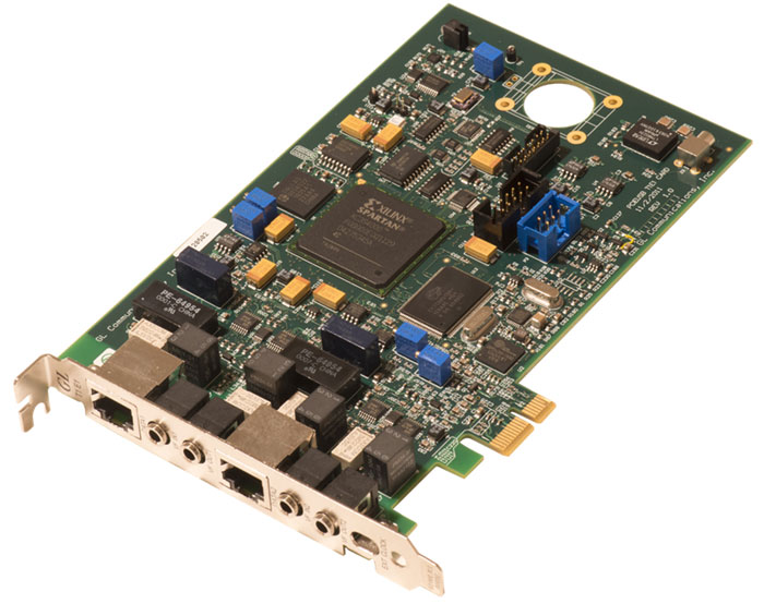
- PCIe Based Express T1 E1 Cards - supports 3.5mm balanced (stereo) analog interfaces with varying impedances.
Caution: Do NOT connect balanced (stereo) signals to unbalanced (mono) signals, i.e. do not connect VF signals between different GL platforms. If you must, then use only mono cables.
Additional details for each are provided below.
- VF Interfaces in tProbe™ T1 E1 & Dual PCIe T1 E1
- VF Input
- VF Output
- VF Tx Rx Gains
- VF TX and RX Impedances
- Typical Applications for VF
- VF Signal Measurements
Summary of Cable Requirements between GL T1E1 products
VF Interfaces in tProbe™ T1 E1 & Dual PCIe T1 E1 Analyzer
GL's tProbe T1/E1 and Dual T1/E1 Express Analyzer products are equipped with VF inputs and outputs via 3.5 mm connectors. Primary functionality of these connectors is to connect to external equipments or accessories. Input signal is digitized (at 8 Khz, uLaw/A-Law) and inserted into selected timeslot of T1/E1. Higher sampling rates (16KHz for 8/16 bits) are under development. Higher resolution at 8 kHz and 16 bits is also available.
An output audio signal is dropped from the selected timeslot of T1/E1. These interfaces offer many termination modes so that it can be compatible with connected source or sink devices under test. It describes details about 3.5mm jack connectivity details and also various impedances offered for termination mode. It is important to select correct impedance settings using Analyzer GUI or scripts so that source and sink present same resistive load and analog signal flow as expected.
VF interfaces on these GL's hardware are balanced interface, which means that analog signal is presented and expected on Tip and Ring of the connector and shield (sleeve) is grounded to chassis as depicted in the following diagrams. It is important to use stereo 3.5mm audio cables when inter-connecting other equipments or accessories into these connectors.
Balanced Audio Cable
A balanced cable uses Tip, Ring for Audio signal and cable shield for the ground.
VF Input:
VF Output:
VF Tx Rx Gains
VF Tx Gains |
Supports: -12 dB to +59 dB in 0.5dB Steps Gain (0.1 dB steps can also be accommodated in tProbe™) |
VF Rx Gains |
Supports: -63.5 dB to +9 dB in 0.5dB Steps Attenuation (0.1 dB steps can also be accommodated in tProbe™) |
VF TX and RX IMPEDANCES
GL's analyzer allows users to select various VF terminations, gain, drop, and insert options within VF Dialog bar as shown below. User should select appropriate impedance settings as per their application.
| VF Imped/Mic Selection |
VF Input Impedance |
VF Output Impedance |
|---|---|---|
135 |
135 Ohms |
135 Ohms |
150 |
150 Ohms |
150 Ohms |
600 |
600 Ohms |
600 Ohms |
900 |
900 Ohms |
900 Ohms |
High |
>50K Ohms |
600 Ohms |
Mic+Headset |
1K Ohms+ |
900 Ohms |
Typical Applications for VF
| Typical Application | VF Imped/Mic Selection |
Recommended Connectivity |
|
|---|---|---|---|
Telephony Audio Equipments |
|
600 |
VF Out jack to Equipment In VF In jack to |
Old Telephony Audio Equipments |
|
900 |
VF Out jack to Equipment In VF In jack |
Connecting VF Input and Output to Sound Card |
|
900 |
-VF Out jack to Line In |
Non-Intrusively Bridge over VF Line |
|
High |
-VF In jack to bridge on line |
Connecting Headset with Microphone for communication over T1/E1 Timeslot |
|
Mic+Headset |
VF-In jack to Mic
|
Wideband Copper Equipments |
|
135 or 150 |
VF Out jack to Equipment In VF In jack |
VF Signal Measurements
tProbe™ VF IN (8 KHz Mu-law encoding) connected to Sage 930A Out using 3.5mm Stereo Cable.
The table below provides a comparison of the VF signal measurements against different impedances between tProbe™ and Sage 930A.
Note: For the below measurements the gain on the VF dialog bar is set to the 0 reference level.
| VF Imped/Mic Selection |
VF Output Impedance on Sage 930A |
1004 Hz Signal Level from Sage-930A | tProbe T1 VF IN Level in Spectral Display dBm |
tProbe T1 VF IN S/N in Spectral Display |
|---|---|---|---|---|
135 |
150 Ohms |
-10 dBm |
-10.8 |
36.5 |
|
|
-15 dBm |
-15.9 |
33.8 |
|
|
-20 dBm |
-21.0 |
29.6 |
150 |
150 Ohms |
-10 dBm |
-10.3 |
36.9 |
|
|
-15 dBm |
-15.4 |
31.3 |
|
|
-20 dBm |
-20.6 |
29.2 |
600 |
600 Ohms |
-10 dBm |
-9.9 |
39.8 |
|
|
-15 dBm |
-14.9 |
38.7 |
|
|
-20 dBm |
-19.9 |
36.6 |
900 |
900 Ohms |
-10 dBm |
-10.0 |
38.9 |
|
|
-15 dBm |
-15.0 |
37.7 |
|
|
-20 dBm |
-20.0 |
37.3 |
|
|
- |
|
|
High |
600 Ohms |
-10 dBm |
-7.3 |
36.6 |
|
|
-15 dBm |
-12.4 |
37.5 |
Special Mic+Headset testing: |
||||
Mic+Headset |
|
-15 dBm |
-4.9 |
34.4 |
|
|
-20 dBm |
-9.9 |
33.7 |
|
|
-25 dBm |
-14.9 |
32.1 |
tProbe™ VF IN Connected with Edirol UA-1ex Soundcard Out Port using 3.5 mm Stereo or Mono Cable:
The table below provides a comparison of the VF signal measurements against different cables between tProbe™ and Edirol UA-1ex Soundcard.
Note: When connected against soundcard, there are many factors which affects true output level like Software Volume Control, Sound Card Volume Control etc.
For the below measurements the gain on the VF dialog bar is set to the 0 reference level.
| VF Impedance | Sound Card Line Output Stereo 1004 Hz at -10 dBm |
Cable | tProbe T1 VF IN Level in Spectral Display dBm |
tProbe T1 VF IN S/N in Spectral Display |
Sage 930A Level Measurement dBm |
|---|---|---|---|---|---|
900 |
Phase Reversed L/R Signal |
Stereo |
-12.4 |
37.7 |
-12.3 |
900 |
Phase Reversed L-R Signal |
Mono |
-13.9 |
39.4 |
-14.0 |
* 900 |
Non-Phase Reversed L-R Signal |
Stereo |
-47.0 |
|
-47.0 |
900 |
Non-Phase Reversed L-R Signal |
Mono |
-15.1 |
39.1 |
-15.2 |
900 |
Stereo Music File |
Stereo |
Sound OK |
|
|
* This is expected result because of same signal fed to Left and Right channel and will be in same phase and will be canceled at transformer input.
tProbe™ VF IN Connected with connected with PC Sound card using 3.5mm Stereo or Mono Cables.
The table below provides a comparison of the VF signal measurements against different cables between tProbe™ and PC Soundcard.
For the below measurements the gain on the VF dialog bar is set to the 0 reference level.
VF Impedance |
Sound Card Line Output Stereo 1004 Hz at -10 dBm |
Cable | tProbe T1 VF IN Level in Spectral Display dBm |
tProbe T1 VF IN S/N in Spectral Display |
Ameritec AM5XT Level Measurement dBm |
|---|---|---|---|---|---|
900 |
Phase Reversed L/R Signal |
Stereo |
-9.9 |
39.1 |
|
900 |
Phase Reversed L-R Signal |
Mono |
-14.6 |
37.1 |
-14.4 |
*900 |
Non-Phase Reversed L-R Signal |
Stereo |
-47.0 |
|
-47.0 |
900 |
Non-Phase Reversed L-R Signal |
Mono |
-14.6 |
36.5 |
-14.4 |
900 |
Stereo Music File |
Stereo |
Sound OK |
|
|
* This is expected result because of same signal fed to Left and Right channel and will be in same phase and will be canceled at transformer input.
tProbe™ VF IN Connected with External Microphone:
Recommended gain of 25 dB on VF-Insert.
Observe signal in spectral display and also drop output to Headset via different timeslot to listen what is spoken on microphone.
tProbe™ VF IN (8 KHz 16-bits encoding) Connected with Sage 930A Output
The table below provides a comparison of the VF signal measurements against different impedances between tProbe™ and Sage 930A.
All the measurement were done after recording 8kHz 16-bits signal into file and than opening that file into Adobe Edition for analysis.
| VF Imped/Mic Selection |
VF Output Impedance on Sage 930A |
1004 Hz Signal Level from Sage-930A | tProbe T1 VF IN Level in dB (Adobe Edition) Stats Peak |
Next Largest Peak In dB (In Adobe Audition) |
Average Noise Floor in dB (Adobe Audition) |
|---|---|---|---|---|---|
135 |
150 Ohms |
-10 dBm |
-13.98 |
-66.27 |
-84 |
|
|
-15 dBm |
-19.04 |
-66.82 |
-84 |
|
|
-20 dBm |
-24.19 |
-66.56 |
-84 |
150 |
150 Ohms |
-10 dBm |
-13.51 |
-74.96 |
-86 |
|
|
-15 dBm |
-18.54 |
-74.96 |
-86 |
|
|
-20 dBm |
-23.74 |
-74-96 |
-86 |
600 |
600 Ohms |
-10 dBm |
-13.18 |
-74.74 |
-96 |
|
|
-15 dBm |
-18.16 |
-79.44 |
-101 |
|
|
-20 dBm |
-23.14 |
-88.53 |
-102 |
900 |
900 Ohms |
-10 dBm |
-13.25 |
-69.93 |
-92 |
|
|
-15 dBm |
-18.24 |
-74.01 |
-108 |
|
|
-20 dBm |
-23.23 |
-80.80 |
-108 |
|
|
- |
|
|
|
High |
600 Ohms |
-10 dBm |
-10.57 |
-67.17 |
-96 |
|
|
-15 dBm |
-15.52 |
-77.83 |
-94 |
|
|
-20 dBm |
-20.55 |
-81.01 |
-101 |
 Back to List of Hardware Platforms Index Page