IP (Layer 3) Testing
PacketExpert™ provides independent Ethernet/VLAN/MPLS/IP/UDP testing at wire speed for applications such as BERT, RFC 2544, and Loopback, also supports optional applications for advanced testing such as Record and Playback, ExpertSAM™, PacketBroker, Multi Stream UDP/TCP Traffic Generator and Analyzer, and ExpertTCP.
Network Layer (Layer 3) uses routing technologies to connect various systems within a network or to connect multiple networks together through Gateways. In Layer 3 testing, packets are routed between the Source and Destination PCs based on both the IP address and MAC address. So, both the MAC address and the IP address must be configured for Layer 3 testing.
Testing at Layer 3 using GL's PacketExpert™ can be accomplished as shown in the figure below. Here, two PacketExpert™ applications operate in separate IP networks and are connected through routers, which route the frames based on the IP addresses in the test frames. Since IP networks encompass various types of physical networks consisting of LAN and WAN links, there is lot of scope for packet modification, packet loss and out of order packets. GL's PacketExpert™ helps measure these metrics of the IP network.
Two test scenarios at Layer 3 are as depicted in the diagram where the information in layer 3 is transmitted through the network in packets.
Scenario 1 - Source & Destination PC are located within the same IP network, and hence are directly reachable
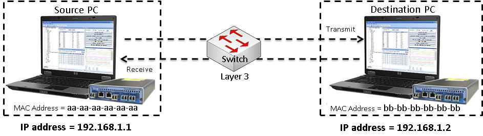
Indirect Routing Test Setup at Layer 3 within the same IP network
Scenario 2 - Source & Destination PC are located at different IP networks, and are connected through routers
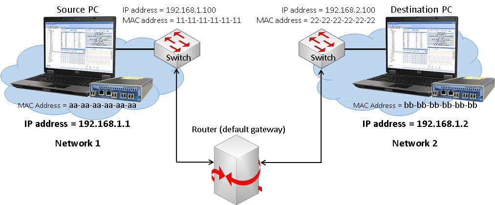
Indirect Routing Test Setup at Layer 3 between different IP networks
IPv4 Configuration
An IPv4 packet consists of a header section and a data section. The header consists of 13 fields, of which the following fields can be configured.
IPv4 Header
Layer3 configuration allows editing source and destination IP Addresses. In addition, users can configure various IP header fields like TOS, TTL, Protocol, Header Checksum, and Identification field. User can choose to allow hardware to calculate/verify checksum or provide a fixed value. IPv6 is also supported.
- Source IP Address: During Tx, Source IP Address is fill-up in the outgoing packet and during Rx, these addresses are used to match with the received packet’s Source and Destination address. If they do not match, the packet is rejected as Non-Test Packet.
- Destination IP Address: IPv4 address of the receiving node
- TOS/DS: Type of Services (ToS)/Differentiated Service an 8-bit field intended to instruct routers how to prioritize traffic. In practice, most routing equipment tends to ignore the TOS/DS field.
- TTL: Time to Live (TTL) is an eight-bit field that determines how many hops a packet can make before it expires.
- Protocol: This field in IP Header defines the protocol used in the data portion of the IP datagram. For Rx config, this is used to filter incoming packets.
- Header Checksum: The 16-bit checksum field is used for error-checking of the header. At each hop, the checksum of the header must be compared to the value of this field. If a header checksum is found to be mismatched, then the packet is discarded.
- Identification: ID fields are also used for adding packet-tracing information to datagrams to help trace spoofed source addresses.
IPv6 Configuration
PacketExpert™ supports Layer 3 IPv6 testing. An IPv6 packet consists of a header section and a payload section. The header is in the first 40 octets (320 bits) of the packet, of which the following fields are allowed to be edited.
IPv6 Header
IPv6 uses 128-bit addresses but is otherwise very similar to IPv4.
- Traffic Class - packet priority (8 bits) – contains Internet traffic priority delivery value.
- Flow Label - (20 bits) - used for specifying special router handling from source to destination(s) for a sequence of packets.
- Next Header - (8 bits) - specifies the next encapsulated protocol. If incoming IPV6 packet’s Next header filed value does not match the configured value, then the packet is rejected and flagged as Non-test packet.
- HOP Limit - (8 bits) - For each router that forwards the packet, the hop limit is decremented by 1. When the hop limit field reaches zero, the packet is discarded.
- Source / Destination Address – (128 bits each) - IPv6 address of the sending / receiving node.
PacketExpert™ provides IP Layer 3 port-wise test results which includes – IP checksum Errors, IPv4 Packets, IPv6 Packets, IP Non-Test Packet, IP, UDP, TCP, ICMP, IGMP, IGRP, and Other Protocols in IP Packet.
IP Statistics
IPv6 Configuration
PacketExpert™ 10GX – Portable
PacketExpert™ 10GX Portable Hardware Unit
| Hardware Specifications | |
|---|---|
Interfaces |
|
Protocols |
|
Bus Interface |
|
External Power Supply |
|
Physical Specification |
|
PacketExpert™ 10GX – Rack
PacketExpert™ High-Density 12/24 GigE Ports
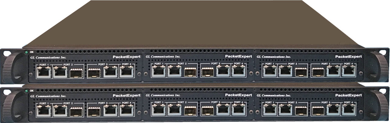
GL also offers rack-based variant using mTOP™ 1U/2U rack mount enclosures within which PacketExpert™ 10GX USB units are stacked to provide high density 12/24 GigE ports form factor solution for testing GigE switches, routers and network conditions. This multi-device hardware unit incorporates all the features of a portable PacketExpert™ 10GX (10G/2.5G/1G ports) unit along with the necessary PC hardware with Windows® OS and remote accessibility via Ethernet Remote Desktop. It is a perfect ethernet test tool for customers who require multi-port testing but are constrained by lab space. For more details on mTOP™ rack-based platform, refer to Test Tools in Rack Based Platforms.
- PacketExpert SA (PXN112) is a 12-Port PacketExpert™ w/ Embedded Single Board Computer (SBC). SBC Specs: Intel Core i3, Win10 Pro 64-bit OS, USB 3.0 Hub, Min 128GB Hard drive, 8G Memory. 19" 1U Rackmount enclosure includes 12-Port PacketExpert™ 10GX w/ MT001 and 3x PXN100 units.
- PacketExpert SA (PXN124) is a 24-Port PacketExpert™ w/ Embedded Single Board Computer (SBC). SBC Specs: Intel Core i3, Win10 Pro 64-bit OS, USB 3.0 Hub, Min 128GB Hard drive, 8G Memory. 19" 2U Rackmount enclosure includes 24-Port PacketExpert™ 10GX w/ MT001, MT002 and 6x PXN100 units.
12 Ports HD PacketExpert™ - mTOP™ PXN100 1U System
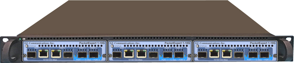
1U mTOP™ with 3x PXN100 USB units (MT001 + PXN100)
24 Ports HD PacketExpert™ - mTOP™ PXN100 1U Stacked System
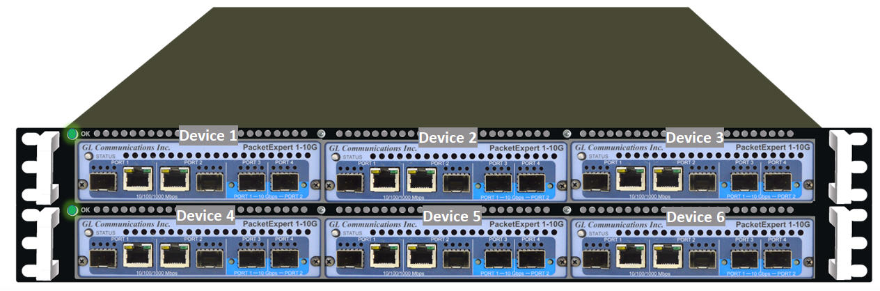
Two-stacked 1U mTOP™ with 6x PXN100 USB units
(MT001 + MT002 + PXN100) – Front Panel View
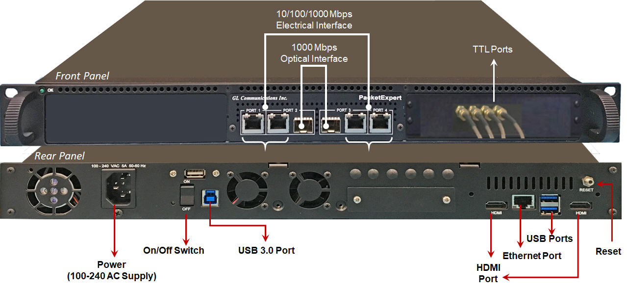
PacketExpert™ 10GX Rack-Mount (MT001) Unit
| Hardware Specifications | |
|---|---|
Interfaces |
|
Embedded PC Specifications |
|
Protocols |
|
Bus Interface |
|
External Power Supply |
|
Physical Specifications |
|
mTOP™ 10G/1G Multi-Port Ethernet Probe
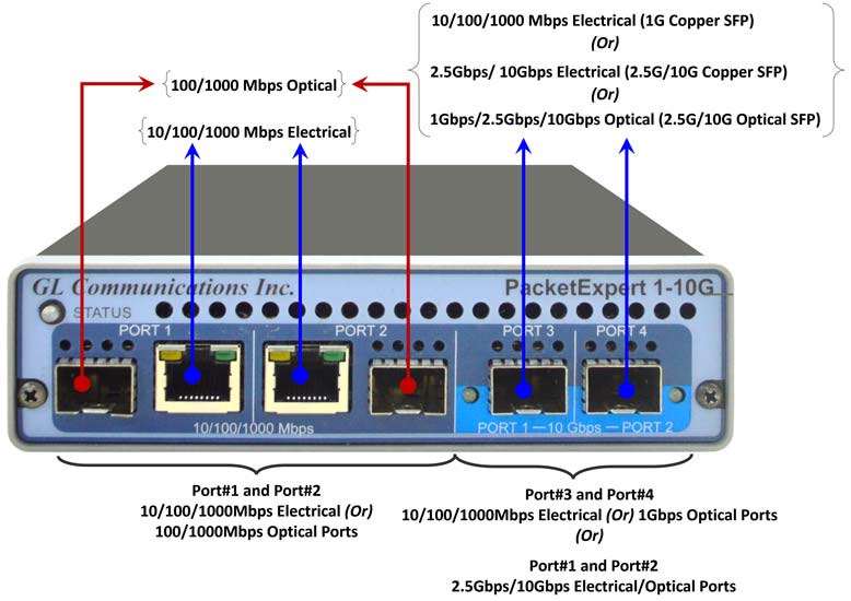
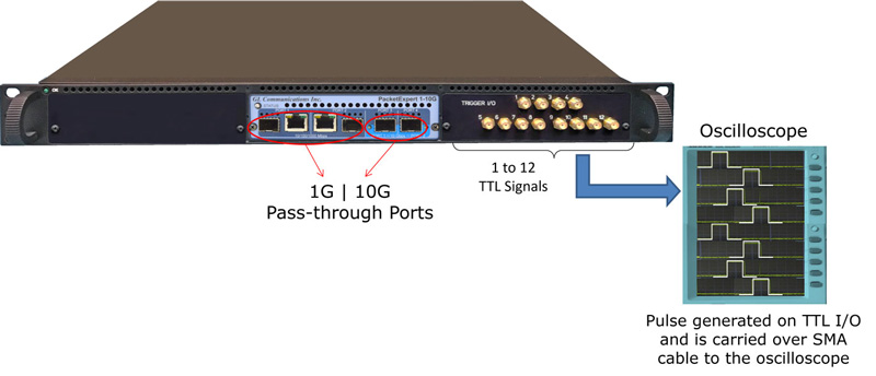
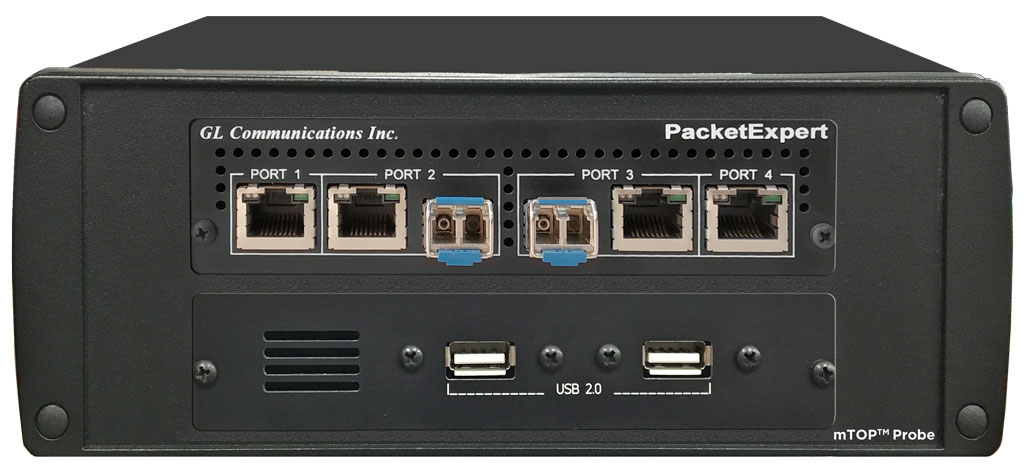
The sleek design of PacketExpert™ 10GX (PXN100) portable hardware allows the unit to be easily placed in a mTOP™ Probe unit which includes necessary SBC making it suitable for field testing. It is a perfect ethernet test tool for customers who require portable and remote accessibility. The PacketExpert™ 10GX hardware interfaces include two 10/2.5/1 Gbps Optical/Electrical ports, and two 10/100/1000 Mbps Electrical/Optical capable ports. The 10/2.5/1 Gbps ports can be down shifted to support 1Gbps Electrical ports, thus offering 4 Electrical / 4 Optical 1 Gbps ports for ethernet testing. The compact hardware unit optionally includes user configurable TTL trigger ports as an important enhancement.
 PacketExpert 10GX (PXN100) mTOP™ Ethernet IP Tester Brochure
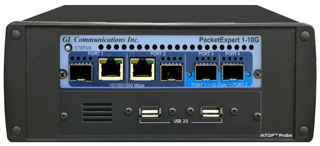
PacketExpert™ 10GX mTOP™ Probe 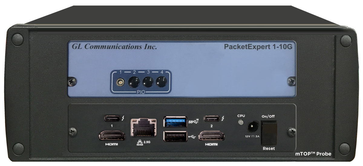
PacketExpert™ 10GX mTOP™ Probe |
|
PacketExpert™ 1G - Portable
PacketExpert™ 1G Portable Unit (PXE100)
Back Panel
Front Panel
Interfaces |
|
Protocols |
|
Bus Interface |
|
Power |
|
Temperature |
|
Humidity |
|
Altitude |
|
Physical Specification |
|
mTOP™ 1G Multi-Port Ethernet Probe
PacketExpert™ mTOP™ Probe is a portable Quad Port Ethernet/VLAN/MPLS/IP/UDP Tester with 4 Electrical Ethernet Ports (10/100/1000 Mbps) and 2 Optical Ports (100/1000 Mbps). Each GigE port provides independent Ethernet/VLAN/MPLS/IP/UDP testing at wire speed for applications such as BERT, RFC 2544, and Loopback. BERT is implemented for all layers. RFC 2544 is applicable for Layers 2, 2.5, and 3, and Loopback is applicable for Layers 2, 3, and 4. Further, PacketExpert™ also supports optional applications for advanced testing such as Record and Playback, ExpertSAM™, PacketBroker, Multi Stream UDP/TCP Traffic Generator and Analyzer, and ExpertTCP™.
It truly takes confusion out of Ethernet / IP testing at all protocol layers - from Layer1 frames to IP/UDP packets. It can be used as a general purpose Ethernet to IP performance analysis tool for 10 Mbps, 100 Mbps and 1 Gbps Ethernet local area networks and wide area networks (WAN).
Two of the 4 ports in the PacketExpert™ unit support both electrical and optical interfaces per unit, enabling testing on optical fiber links as well. The electrical ports support 10/100/1000 Mbps, and optical ports support 100/1000 Mbps using SFP. The embedded SBC makes it conveniently be used for field testing.
PacketExpert™ 1G Multi-Port Ethernet IP Tester Brochure
PacketExpert™ 1G mTOP™ Probe 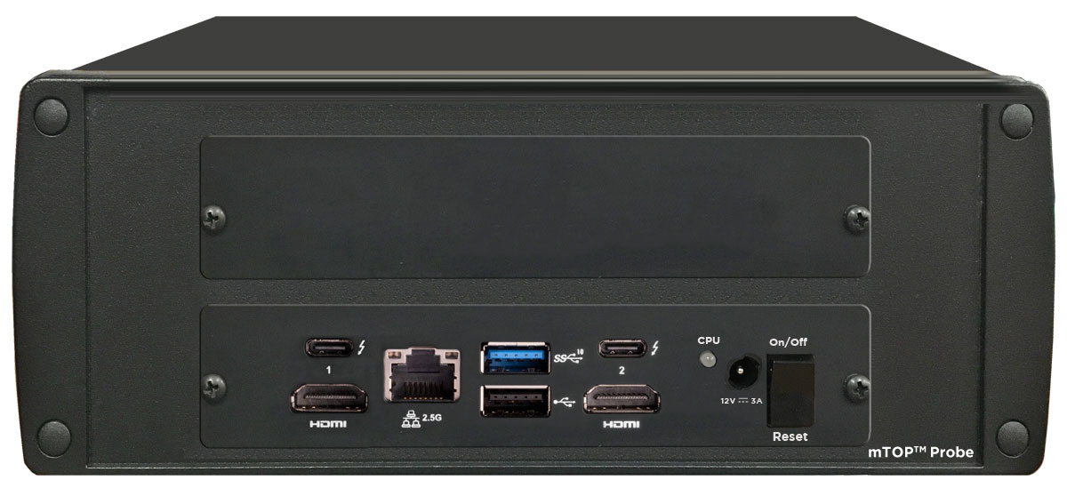
PacketExpert™ 1G mTOP™ Probe |
Refer to Packet /Ethernet Series Price Lists |
PacketExpert™ 1G - Rack (*Legacy Products)
PacketExpert™ 1G Rack Unit
PacketExpert SA (PXE104) |
4-Port PacketExpert™ w/ Embedded Single Board Computer (SBC). |
Interface: |
4 Total Ethernet ports |
Dimension: |
Length: 16 Inches |
Power Source: |
120-230 AC Power Supply |
Connectivity: |
2 x USB 2.0 (or 10/100 Mbps Management Ethernet) |
Packet Analyzer
Measuring delay, jitter and packet loss through these networks is critical and network testers will need to precisely time events. Understanding the time from which the Air Traffic Controller keys PTT until the IP stream indicates that the PTT bit is set is a relevant testing scenario. This delay measurement is possible using GL’s Packet Analyzer - PacketExpert™. The Packet Analyzer is capable of generating event driven triggers based on certain packet filters. For each packet that satisfies filter criteria that will be forwarded for timestamping and synchronizing with other equipment.
Packet Analyzer hardware is capable of modifying the filtered packets using an inband method to convey information such as Timestamp (8 Bytes), Board Serial No. (1 Byte), Port No. (4 Bits), and Filter No. (2 bytes), to the output ports in the packet's MAC header.
PacketExpert SA (PXE104) |
4-Port PacketExpert™ w/ Embedded Single Board Computer (SBC). |
Interface: |
4 Total Ethernet ports |
Dimension: |
Length: 16 Inches |
Power Source: |
120-230 AC Power Supply |
Connectivity: |
2 x USB 2.0 (or 10/100 Mbps Management Ethernet) |
Buyer's Guide
| Item | Description |
|---|---|
| PXN100 | PacketExpert™ 10GX |
| PXN101 | 10G option for PXN100 |
| CXN100 | CLI Server for PXN100 |
| PXN112 | PacketExpert™ 10GX – SA (12-Port) |
| PXN124 | PacketExpert™ 10GX – SA (24-Port) |
| PXN105 | PacketExpert™ Wirespeed Record / Playback for PXN100 |
| PXN106 | ExpertSAM™ - for PXN100 |
| PXN107 | PacketBroker™ - for PXN100 |
| PXN108 | Multi-Stream UDP/TCP Traffic Generator and Analyzer – for PXN100 |
| IPN507 | IPNetSim™ & IPLinkSim™ Options for 1G, 2.5G and 10G |
| Item | Description |
|---|---|
| PXE100 | PacketExpert™ 1G |
| CXE100 | CLI Server for PXE100 |
| PXE104 | PacketExpert™ - SA (4 ports) |
| PXE112 | PacketExpert™ - SA (12 Ports) |
| PXE124 | PacketExpert™ - SA (24 Ports) |
| PXE105 | PacketExpert™ Wire speed Record /Playback for PXE100 |
| PXE106 | ExpertSAM™ - for PXE100 |
| PXE107 | PacketBroker™ - for PXE100 |
| PXE108 | Multi-Stream UDP/TCP Traffic Generator and Analyzer - for PXE100 (up to 12 users) |
Resources
| PacketExpert™ 10GX - Brochures |
|---|
|
PacketExpert™ 10GX - ExpertSAM PacketExpert™ 10GX - ExpertTCP PacketExpert™ 10GX - PacketBroker |
| PacketExpert™ 10GX - Presentations |
|---|
|
PacketExpert™ 10GX - ExpertSAM PacketExpert™ 10GX - ExpertTCP |