PacketBroker – Active Ethernet Tap
Highly precise wirespeed Ethernet tap used to capture and filter real world traffic, generate triggers based on filters, and transmit filtered/aggregated/modified packets for deep packet inspection.
Request a Demo / Quote Brochure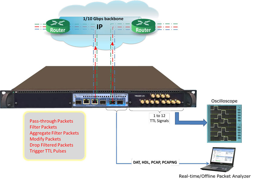
Overview
PacketBroker is an optional application on GL's PacketExpert™ hardware platform. It allows the Ethernet test tool to be used as a highly precise non-intrusive wirespeed Ethernet tap to capture real world traffic, define filters for drilling-down to traffic of interest, generate triggers based on packet filters, and transmit the filtered/aggregated/modified packets for deep packet inspection.
PacketBroker is an Active Ethernet Tap where the incoming frames Ethernet FCS is checked and the frames with bad FCS are dropped. The frames with valid FCS are taken up for processing after the FCS is stripped off. After processing, while sending the packet out of the opposite port, the FCS is recalculated and attached to the outgoing Ethernet frame.
The PacketBroker application utilizes all these ports to support advanced features such as -
- Network Tap - capable of handling bidirectional 100% wirespeed traffic up to 10 Gbps
- Wirespeed Filtering - powerful and easy to use
- Packet Modification to convey useful information like Timestamp, Filter number etc. inband
- TTL Trigger I/O - generates or accept TTL signals based on packet filters
- Output aggregation - both direction traffic multiplexed on the same output port

PacketBroker is available on all the PacketExpert™ platform variants -
- PacketExpert™ 1G (PXE100) - This is a quad port USB based portable unit, of which 2 ports are of 10/100/1000Mbps Electrical or Optical (Port 2, Port 3), and other 2 are 10/100/1000Mbps Electrical only. The application captures on the 10/100/1000Mbps Electrical/Optical ports (Pass-through ports) and outputs the filtered and modified packets on output ports (Port1 and Port4) respectively or aggregates the output to either Port1 or Port4. All the features of high-end taps are packaged into this portable unit making it suitable for field testing and remote testing any point in the network.
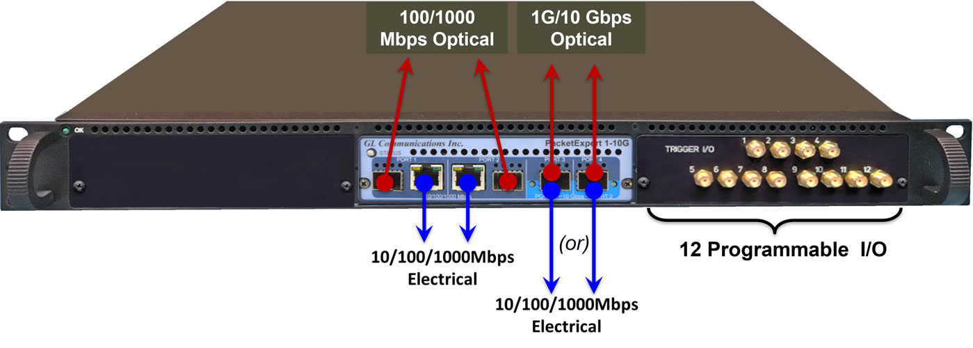
- PacketExpert™ 10GX (PXN100) - This is a quad port USB based portable unit, of which 2 are 10/2.5/1 Gbps Electrical/Optical ports, and other 2 are 10/100/1000Mbps Electrical/Optical ports. The 10/2.5/1 Gbps ports can be down-shifted to support 1Gbps Electrical ports, thus offering 4 Electrical / 4 Optical 1 Gbps ports for ethernet testing. The application captures on 10/2.5/1 Gbps optical/electrical ports (Pass-through ports) and outputs the filtered and modified packets is either aggregated or individually output on 1 Gbps Electrical/Optical port. And when 1Gbps ports are configured to capture (pass-through ports), the filtered/aggregated/modified packets are output on 1Gbps ports only. Thus, operating in all 1Gbps ports mode. The portable unit is suitable for field testing; while the compact design of the unit allows to easily deploy multiple such units in the rack enclosure providing high-density form factor solution.
The traffic on the output ports can be analyzed using packet analyzers such as PacketScan™-All IP analyzer or Wireshark®.
PacketExpert™ also supports Command line Interface (CLI) to access all the functionalities remotely such as Bert, Loopback, RFC 2544, Record Playback, IPNetSim™, IPLinkSim™, ExpertSAM™, PacketBroker, ExpertTCP™, and Multi-Stream Traffic Generator and Analyzer using C#, Python, clients and MAPS™ CLI Server/Client Architecture.
Features
Capture |
|
Filters |
|
Packet Modification |
|
Aggregation |
|
Output |
|
Statistics |
|
CLI (Command Line Interfaces) |
|
Working Principle - (4x 1Gbps ports or 2x 10Gbps ports)
10G ports in Pass-through mode and 1G ports are Output ports
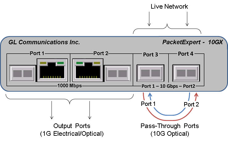
The PacketExpert™ 10GX hardware unit is equipped with both Electrical/Optical ports (1000 Mbps and 10/2.5/1G). The 10G: Port 1 and Port 2 optical/electrical ports can be configured in Pass-through mode, and the 1G: Port1 and Port2 is used in either SFP or Electrical mode to act as output ports.
1G ports in Pass-through mode and 10G ports are Output ports
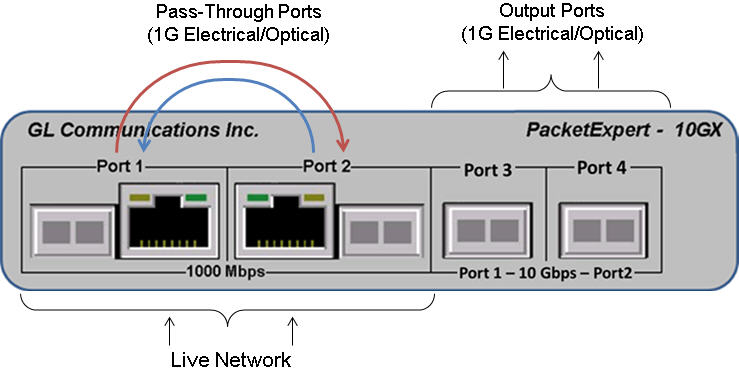
Similarly, the 1G: Port 1 and Port 2 can be used in either SFP or Electrical mode, which when configured in Pass-through mode, the 1G: Port3 and Port4 optical or Electrical ports act as output ports. Thus, all 4 ports on the unit is operating in 1Gbps.
The Output ports on the unit in any of the above configurations can be connected to an external storage device or to an analyzer for detail traffic analysis.
It is important to notice that although Pass-through ports and Output ports are both labelled with the port numbers, they are not interchangeable. Pass-through and Output ports have a fixed role and their purpose cannot be configured by users.
- Pass Through Ports (2): Span ports can be either 1G or 10G ports
In 10G mode, the Dual SFP 10 Gb/s ports (10G: Port#1, Port#2), are generally connected in Pass Through to tap the network under test.
In 1G mode, the Dual RJ-45 ports (1G: Port#1, Port#2) for electrical connection 10/100/1000BASE-T. Dual SFP ports for optical connection 1000 Mbps are connected in Pass Through to capture the network traffic.
- Output Ports (2): Drop ports can only be 1G
In 10G mode, Dual SFP or RJ-45 (1G: Port#1, Port#2) based 1 Gb/s ports are used as Output Ports to forward capture packets to real-time packet analyzer.
In 1G mode, Dual SFP based 10 Gb/s ports (1G: Port#3, Port#4) can be down-shifted to support 1Gbps (Electrical/Optical) ports, thus offering 4 Electrical / 4 Optical 1 Gbps ports for testing.
|
Span (Pass-through) Ports | Drop (Output) Ports |
|---|---|---|
| 10G ports | 10G: Port#1, Port#2 Optical/electrical Ports |
1G: Port#1, Port#2 Electrical/Optical Ports |
| 1G ports | 1G: Port#1, Port#2 Electrical/Optical Ports |
1G: Port#3, Port#4 Electrical/Optical Ports |
The PacketBroker application, allows PacketExpert™ 10GX to capture packets at wirespeed (up to 10 Gbps) non-intrusively over Optical ports at nano-second precision. It supports Tapping (Pass through mode) and Filter-Aggregate-Modification of the captured packets.
The 1G Electrical/Optical ports of the PacketExpert™ 10GX hardware can also be configured to non-intrusively capture network traffic at wirespeed.
PacketExpert™ operation is bi-directional, which means that both transmission directions are simultaneously processed by the equipment.
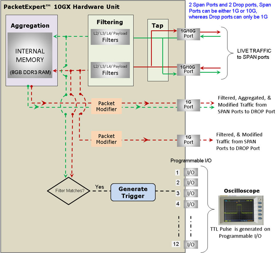
10G/2.5/1G - Tap, Filter, Aggregation, Packet Modification
- Tap: Traffic is forwarded between the Pass-through 10G/2.5/1G ports (Port 1 and Port 2) without any modification or delay, except processing the Ethernet FCS. The incoming frames' Ethernet FCS is checked and the frames with bad FCS are dropped. The frames with valid FCS are sent to the opposite port after stripping off the FCS. While sending the packet out of the opposite port, the FCS is recalculated and attached to the outgoing Ethernet frame
- Filter: Supports wire-speed filtering of Layer2/Layer3/Layer 4 Ethernet packets, with each port featuring up to 16 simultaneous filters each of 120 bytes in length. Mono Trigger and Continuous filter modes are also supported. Filter can be set to any offset within the packet, which gives flexibility to filter any header field as well as the payload
- Packet Modification: PacketExpert™ 10GX hardware modifies the filtered packets using an inband method of conveying information such as Timestamp (8 Bytes), Board Serial No. (1 Byte), Port No. (4 Bits), and Filter No. (2 bytes), to the (1G output ports) packet analyzer carrying this information in the packet's MAC header. The filtered packet's MAC header's Destination MAC Address (6 bytes) and Source MAC Address (6 bytes) fields are modified as below:
- Aggregation & Output: The 10G/2.5/1G port 1 (Pass-through port) traffic filtered is normally sent out on 1G port1/1G port3 (Output port). Similarly, 10G/2.5/1G port2 traffic filtered is sent out on 1G port2/1G port4. Alternatively, the filtered traffic from both 10G/2.5/1G ports can be aggregated and sent out on a single 1G port as a single stream. Since the aggregated stream rate can exceed wirespeed rate of a single port, the aggregated traffic is buffered in the onboard 8 GB DDR3 RAM memory, before being sent out
The traffic on Pass-through ports is filtered and is sent to Packet Modifier, which is then sent out on Output port. The Pass-through ports can be 10G/2.5/1G while the output ports can be only 1G ports. So, the traffic on Output ports are Filtered and Modified Traffic from pass-through ports
Hardware Modified Ethernet Packet Fields
Working Principle - 1G Ports
The PacketExpert™ hardware unit is equipped with both RJ-45 ports (Electrical) and SFP ports (Optical). The Port 2 and Port 3 can be used in either SFP or Electrical mode, and are generally called as Pass-through ports.
The Ports 1 and Port 4 are RJ-45 ports, and are generally called as the Output ports. When these are used, connect the PacketExpert™ unit with an external storage device or an analyzer.
It is important to notice that although Pass-through ports and Output ports are both labelled with the port numbers, they are not interchangeable. Pass-through and Output ports have a fixed role and their purpose cannot be configured by users.
- Pass Through Ports (2): Dual SFP or RJ-45 based 1 Gb/s ports. The Ports 2 and 3, are generally connected in Pass Through Mode to tap the network under test.
- Output Ports (2): Dual RJ-45 ports for electrical connection 10/100/1000BASE-T. The Output Ports interfaces are used to forward captured packets to real-time packet analyzer.
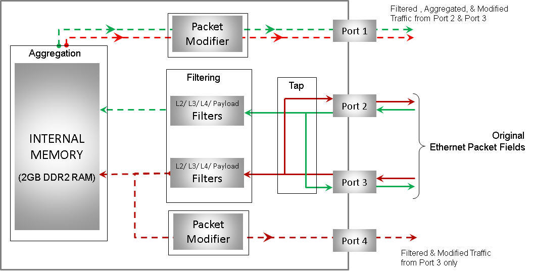
The schematic picture summarizes the different functions such as tap, filter, packet modification, and aggregation of PacketExpert™ (up to 1000 Mbps) PacketBroker application.
The tap, filter, packet modification, and aggregation modes of PacketExpert™ are detailed below:
1G - Tap, Filter, Aggregation, Packet Modification
- Tap: Traffic is forwarded between the Pass-through ports (Port 2 and Port 3) without any modification or delay, except processing the Ethernet FCS. The incoming frames' Ethernet FCS is checked and the frames with bad FCS are dropped. The frames with valid FCS are sent to the opposite port after stripping off the FCS. While sending the packet out of the opposite port, the FCS is recalculated and attached to the outgoing Ethernet frame
- Filter: It supports wirespeed filtering of Layer 2/ Layer 3/ Layer 4 Ethernet packets, with each port featuring up to 16 simultaneous filters each of 40 bytes in length. Mono Trigger and Continuous filter modes are also supported. Filter can be set to any offset within the packet, which gives flexibility to filter any header field as well as the payload
- Aggregation: The Port2 (pass-through port) traffic filtered is normally sent out on Port1 (output port). Similarly, Port3 traffic filtered is sent out on Port4. Alternatively, the filtered traffic from both Port 2 and Port 3 can be aggregated and sent out on a single port as a single stream. Since the aggregated stream rate can exceed wirespeed rate of a single port, the aggregated traffic is buffered in the onboard 2 GB DDR2 RAM memory, before being sent out.
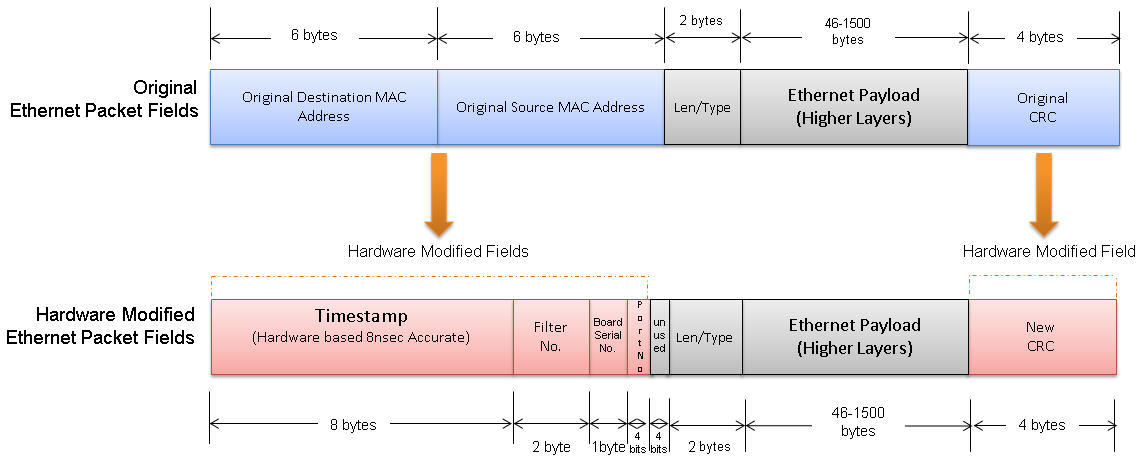
- Packet Modification: Filtered packets can be modified to insert useful information within the packet itself. PacketBroker uses an inband method of conveying this information to the packet analyzer by carrying this information in the packet's MAC header itself. The filtered packet's MAC header's Destination MAC Address (6 bytes) and Source MAC Address (6 bytes) fields are modified as below:
Hardware Modified Ethernet Packet Fields
The PacketExpert™ hardware modifies the received packets and replaces the Source and Destination MAC Addresses (of 12 bytes) fields with Timestamp (8 bytes), Filter No. (2 bytes), Board Serial No. (1 byte), and Port No (4 bits) fields. 4 bits at the end are unused and is set to Zero. The new CRC (4 bytes) is calculated for the modified fields and is appended
Filter Configuration - Filtering Mode
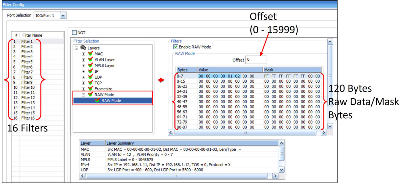
Wirespeed filter within PacketBroker supports Raw Mode and Packet Mode filter configurations. Filter can be set to each bit in the packet (Raw mode) or each field (Packet Mode). It is possible to configure up to 16 filters on 1G ports and 4 filters on 10G ports.
In Raw mode, each bit can be set to "Filtered" or "Don't care" condition via filter mask. Each filter has 2 sets (Value and Mask) each of 120 bytes length. Value contains the actual filter data used for comparing. Mask is used to indicate the bit/bytes to be compared or ignored. Various packet field values can be edited directly as per the layer stack (L2/L3/L4) selected.
For each filter, offset can be set to any byte within the packet (from 0 to 15999 ) which gives flexibility to filter any field within any protocol header, or even the payload.
Up to 16 simultaneous filters can be applied per port with “AND” /”OR” condition set to combine all the filters. Further, each filter can be set to either Accept or Reject the packet.
In Packet mode, the user can create filters if layer stack of the incoming packets is known, then the filter can be set for individual fields. The supported layer stack and the editable parameters for each of the layer is as below:
- MAC Layer Filtering – for MAC layer, Hex fields like Source and Destination MAC Addresses, and Len/Type layer parameters can be edited individually with the value and mask.
- VLAN layer Filtering - For VLAN Layer, VLAN Id field can be filtered by specifying the fixed value, or providing the range, or setting it to ANY.
- MPLS Layer Filtering - for MPLS layer, the MPLS stack parameter (MPLS Label) can be filtered by specifying the fixed value, or providing the range, or setting it to ANY.
- IP Layer Filtering - for IP layer, the IP layer Source and Destination Address parameters can be filtered by specifying the fixed value, or providing the range, or setting it to ANY.
- UDP Layer Filtering – for UDP layer, Source and Destination ports can be filtered by specifying the fixed value, or providing the range, or setting it to ANY.
Filter Editing in Raw Mode
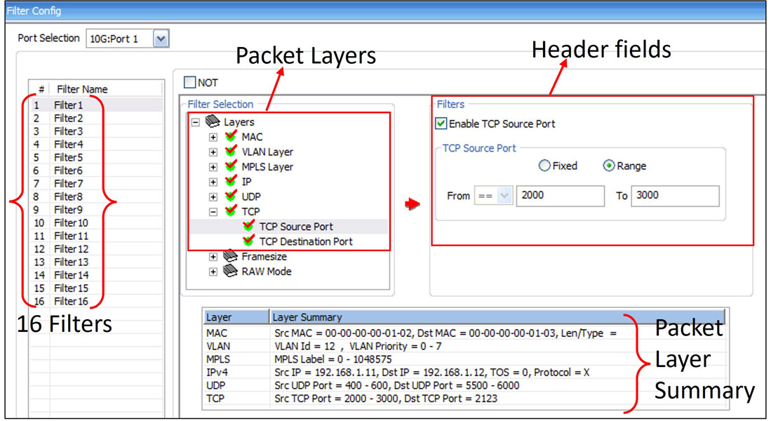
Filter Editing in Packet Mode
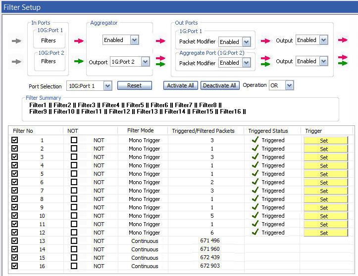
Continuous/Mono Trigger Packet Filter Mode
Each filter can be configured to run in either mono trigger or continuous filter mode.
Continuous mode is the normal filter operation mode where packets are set to filter continuously. In Mono Trigger filter mode, once the packet that matches the filter is filtered, filtering is stopped and, any further packets are not accepted, even if they match the filter. The first single matching packet is said to have “triggered” the filter. User can set the trigger again manually at run time. Correspondingly, Triggered/Filtered Packets statistics are logged.
Filter Configuration - Filter Grouping Mode
The filter configuration within PacketBroker is enhanced to support grouping the configured filters. Individual filters are setup while the PacketBroker is running in Normal / Basic mode.
Individual filters can be combined into groups using "OR" or "AND" operations. Groups of filters can be further combined into "Super Groups" again using "OR" or "AND". Maximum of 16 groups can be setup on 1G ports.
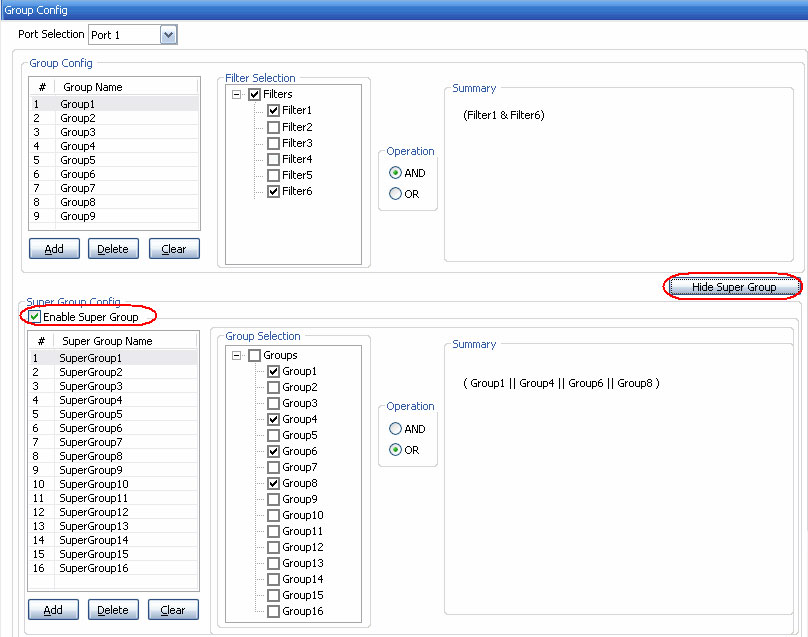
Filter Grouping and Super Grouping Configurations
Each filter Super Group can be configured to run in either mono trigger (manual mode) or continuous filter mode (automated).
Continuous mode is the normal filter operation mode where packets are set to filter continuously. Correspondingly, Triggered/Filtered Packets statistics are logged. In Mono Trigger filter mode, once the packet that matches the super group filter is filtered, filtering is stopped and, any further packets are not accepted, even if they match the filter.
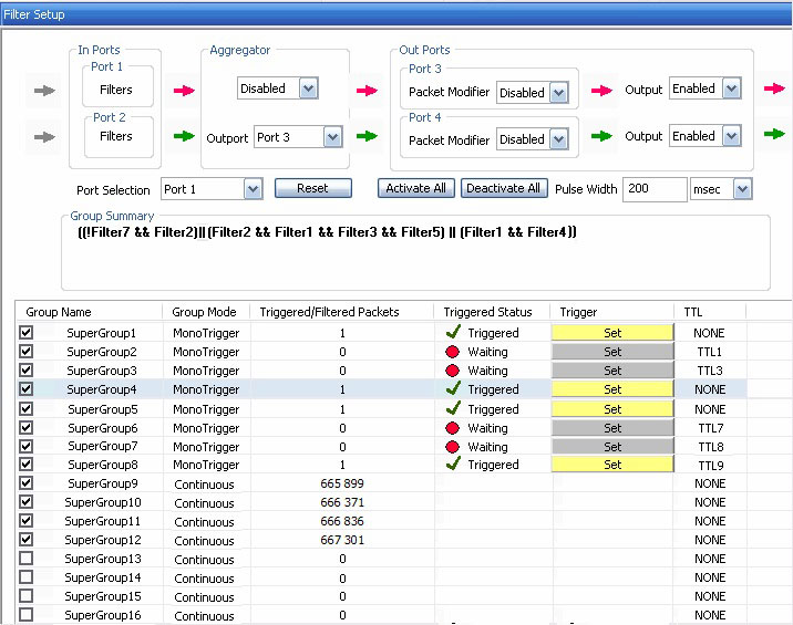
Filter Triggers for Super Group filtering
TTL Pulse Generation
PacketBroker application is now supports generating output TTL signal pulses for every filter/group match.
PacketExpert™ 10GX Hardware includes 12 Programmable TTL I/O (Input/Output) ports. User-configurable Filter/group to TTL Mapping is supported. The 12 TTL (TTL1 to TTL12) ports can be uniquely assigned to filter groups. The length of the TTL signal pulse generated can be customized in msec. User can also choose not to output the generated TTL signal pulse generated for the filter match.
As indicated in the image, the TTL signal (representing the Filter match) can be taken out and processed using an external device like Oscilloscope.
Packet Modification
The PacketExpert™ hardware modifies the received Original Ethernet packets at pass-through ports and replaces the Source and Destination MAC Addresses (of 12 bytes) fields with Timestamp (8 bytes), Filter No (2 bytes), Board Serial No. (1 byte), and Port No (4 bits) fields as shown in the figure. The new CRC (4 bytes) is calculated for the modified fields and is appended. The Hardware modified packets are then sent on Output ports.
The 1 byte “Board Serial Number” field can be configured to either take the Board serial number automatically from the connected PacketExpert™ unit or user can manually configure own numbering. This helps in identifying which PacketExpert™ board captured the packet, useful especially when multi devices are connected.
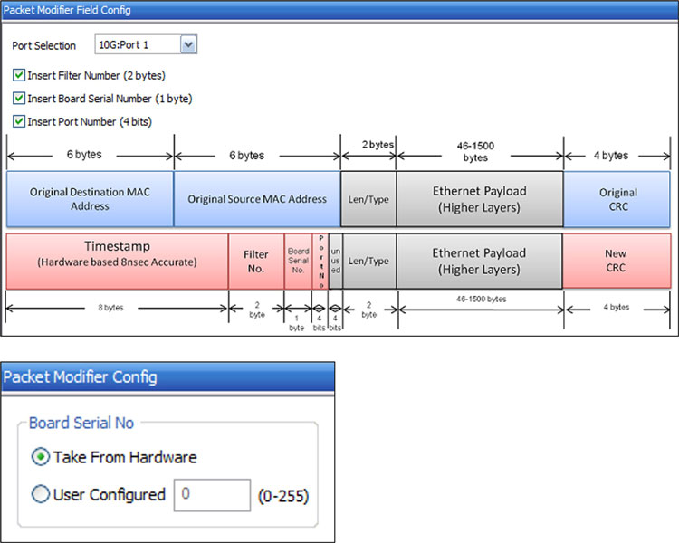
Packet Modification Field Configurations
Port Statistics
| PacketExpert™ 10/1G |
|---|
Detailed Tx Rx frame statistics per port are provided. In addition to statistics like Frame Count, Frame Rate, Link Utilization, other statistics like Frame Type (Unicast/Broadcast/Multicast, VLAN), frame lengths (64, 65-127, 1024-1518, Oversized, Undersized), and FCS Error Frames are also provided. 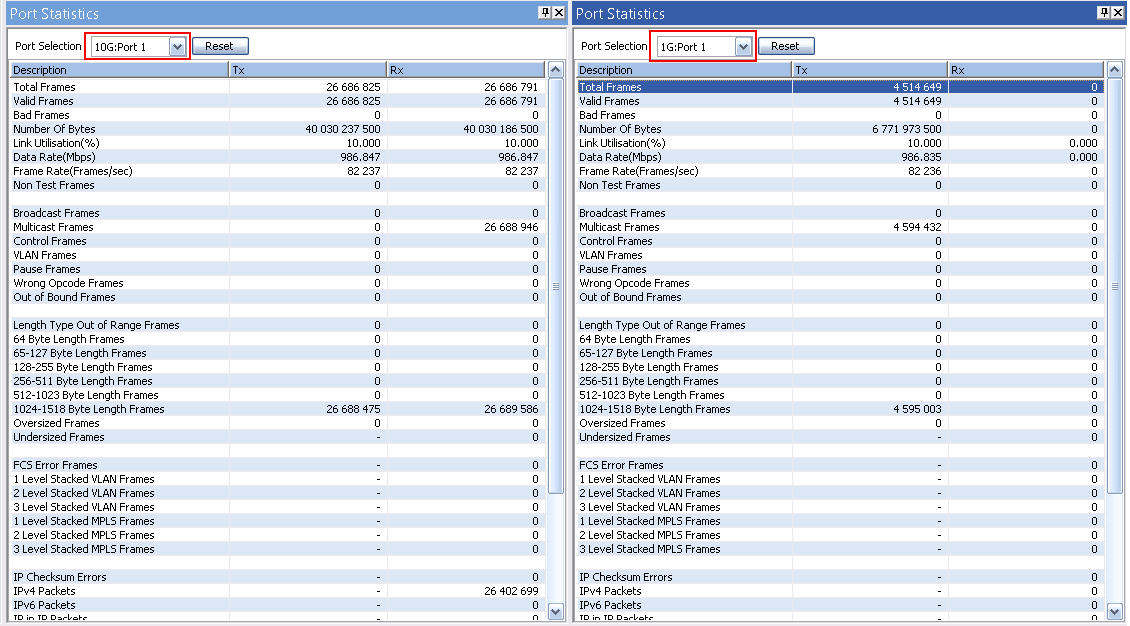 10G/ 1G Port Statistics |
| PacketExpert™ 1G |
|---|
The following figure displays Tx and Rx port-wise statistics for 1G: Port3. 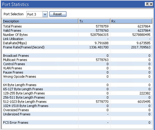
1G Port Statistics |
Resources
Note: PCs which include GL hardware/software require Intel or AMD processors for compliance.
Please Note: The 'Pxx' in the Item No. refers to the hardware platform on which the software will be running. Therefore, 'Pxx' can either be PXE (1G) or PXG (10G) or PXN (10GX) depending upon the hardware.
| Item | Description |
|---|---|
| PXN100 | PacketExpert™ 10GX |
| PXE100 | PacketExpert™ 1G |
| PXN107 | PacketBroker™ - for PXN100 |
| PXE107 | PacketBroker™ - for PXE100 |
| CXN100 | CLI Server for PXN100 |
| CXE100 | CLI Server for PXE100 |
| PacketExpert™ 10GX - Brochures |
|---|
| PacketExpert™ 10GX |
| PacketExpert™ 10GX - PacketBroker |
| PacketExpert™ 10GX mTOP™ |
| PacketExpert™ 10GX CLI |
| PacketExpert™ 1G - Brochures |
| PacketExpert™ 1G |
| PacketExpert™ 1G - PacketBroker |
| PacketExpert™ 1G - mTOP™ |
| PacketExpert™ 10GX - Presentations |
| PacketExpert™ 10GX |
| PacketExpert™ 10GX - PacketBroker |
| PacketExpert™ 1G - Presentations |
| PacketExpert™ 1G |
| PacketExpert™ 1G - PacketBroker |