MFC-R2 Analysis and Emulation
Overview
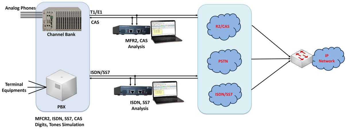
Multi-Frequency Compelled R2 (MFC-R2) signaling is a Channel Associated Signaling (CAS) protocol used over E1 signaling networks.
"Compelled" is to convey that each digit transmission and cessation of transmission is controlled and acknowledged by the receiver of the digit. MFC-R2 is used to convey addressing information along a telephone trunk between two switches in order to establish a telephone call along that path.
MFC-R2 - Compelling signaling
The inbound tones are exchanged between two switches in compelled way.
In the E1 world, CAS protocols use Timeslot 16 for line signaling (also called supervision) - on hook, off hook, seizure, seizure ack, etc. Dual tones representing digits are used for called and calling numbers, sometimes called ANI (Automatic Number Identification) and DID (Direct Inward Dialing).
Different types of signals are exchanged between two switches in the process of establishing a call and those can be broadly classified as Line Signals and Inter Register Signals.
- Line Signals - Allows for the possible signaling states used to set up and clear down the call, and various other events
- Line Signals are the ABCD bits of CAS in timeslot 16, which represents the states of the line. Although E1 Channel Associated Signaling (CAS) framing supports 4 signaling bits, only 2 of them (per direction) are used for R2 line signaling. Thus the signaling channels supporting the R2 line signaling protocol are referred to as Af and Bf in the forward direction, and Ab and Bb, in the backward direction. The forward channel indicates the condition of the outgoing switch equipment and reflects the condition of the calling party's line. The backward channel indicates the condition of the called party's line. The following table summarizes the signaling states of a typical call
Different MFC-R2 Line Signaling states are as listed in the table
- Inter Register signals – Allows selection signals and digits. The digits are used primarily to indicate the called number, but can also have other meanings. Signals sent by the originating point (switch) are called forward and signals sent by the terminating point are called backward)
- These are 2 out of 6 inband multi-tone signals sent in both directions associated with the registers used to control the switching process. Some country specific implementations use less number of frequencies in the set. For example, India uses 2 out of 5 frequencies resulting in a total of 10 different tones for forward and backward signals respectively. (Signals sent by the originating point (switch) are called forward and signals sent by the terminating point are called backward) Each (forward and backward) has two lookup tables to assign/decode the meaning of each tone. They are Tables I and II for forward and A and B for backward.) The below Tables summarize the meanings of each of the tones. The meanings can however vary based on country specific implementation
Register forward Signal look-up table
Register backward Signal look-up table
Typical MFC-R2 call flow is as below
Applications
- Establish MFC-R2 Calls using handset
- Determine addressing formats between exchanges
- Test & analyze MFC-R2 addressing formats
- Manually test MFC-R2 implementations
- Test forward capabilities using automated backward sequences
Features
- Sends MFC-R2 forward and backward tones per CCITT specifications
- Mimics the compelled network
- Establishes calls manually or automatically
- Time-slot selectable
- Record communication exchanges to log file
MFC-R2 Emulation Solutions
- MAPS™ CAS Protocol Emulator (Scripted Channel Associated Signaling (CAS) Emulation)
MAPS™ CAS Emulator is a client-side application that works along with GL's T1 E1 Analyzer Cards and Windows Client/Server software. This test tool is used to perform testing using CAS signaling and transmission and detection of TDM traffic over T1 E1 using scripts, and offers a complete solution for testing, troubleshooting, and maintenance of devices and networks implementing CAS. MAPS™ CAS Simulator supports various CAS protocols such as T1 Wink Start (R1 wink), T1 Loop Start, T1 Ground Start, T1 Feature Group D, T1 Immediate Start, E1 MFC-R2, E1 European Digital CAS (EUC), E1 Digital E & M, E1 International Wink Start, and any user-defined CAS protocol
E1 MFC-R2 Signaling (All variants, full /semi compelled), defined by the ITU Recommendations Q.421-Q.442, uses a multi-frequency compelled signaling protocol to exchange address information Visit MAPS™ CAS Protocol Emulator (Scripted Channel Associated Signaling (CAS) Emulation) for more details
- DTMF / MF / MFR2 / Detector and Generator Software (XX022)
The detector application detects and displays in real-time DTMF, MF, MFR2-forward, and MFR2-backward digits as they are received. The generator application can generate the same digits along with signaling bits, however true compelled operation is not performed. Real-time bi-directional detection of MFR2 forward and backward digits is possible with two instances of the capture application
- Client Server Based Channel Associated Signaling (CAS) Emulation (xx625)
GL's Windows Client/Server makes the T1 E1 Analyzer as server and allows performing of typical tasks such as real time recording and transmission to/from files, dtmf/mf/mfr2 digit detection and generation, bit error rate testing, alarm monitoring, Digital Signal Processing (DSP) operations, ds0 power monitoring, and protocol decoding from multiple client locations
GL's CAS simulator is a client-side application that works along with the GL's T1 E1 Analyzer. It can simulate and analyze any user user-defined CAS protocols by providing signaling bit transitions and forward/backward frequency tones/digits. In addition to generating/receiving CAS calls, the CAS simulator also processes the receipt of Dialed Number Identification Service (DNIS) and Automatic Number Identification (ANI) information. Supported protocols include E1 MFC-R2, T1 Winkstart, T1 Loopstart and Groundstart, E1 European Digital CAS, and any User-defined CAS
MFC-R2 detection and analysis can be done through simple scripts transmitted to the server or using the VB GUI Client described above. VB Client is a Visual Basic GUI Client that connects to the GL Server and performs MFC-R2 signaling and digit analysis and other functions. Visit Client Server and CAS Simulator web pages for more details
MFC-R2 Analysis Solutions
- MFC-R2 Call Capture and Analysis (XX031)
This software permits automatic capture of calls in systems using MFC-R2 protocol. The user can use signaling bits to trigger the start and stop of capture. Both directions of the call are captured in an "east" and "west" file along with a "signaling" file. All inband PCM data is captured including digits and voice
A special DOS application is provided for MFC-R2 digit analysis (r2ana.exe). With this software captured files can be analyzed for R2 tones and signaling. Forward and backward paired tones are detected and displayed with time stamped indications of digit durations and signaling changes. Call duration, timeslot, date, and time of occurrence are also recorded
- Signaling Bits Recorder Software (XX050)
This optional software provides time stamped indications of all signaling bit changes. User has the choice of recording the data from selected channels or from all the channels
- Real-Time Strip Chart (XX024)
This is a real-time graphical application that captures signaling as well as PCM data. Timing relationship of signaling bits and MFC-R2 digits can be easily viewed and analyzed
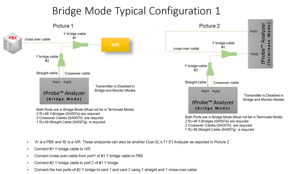
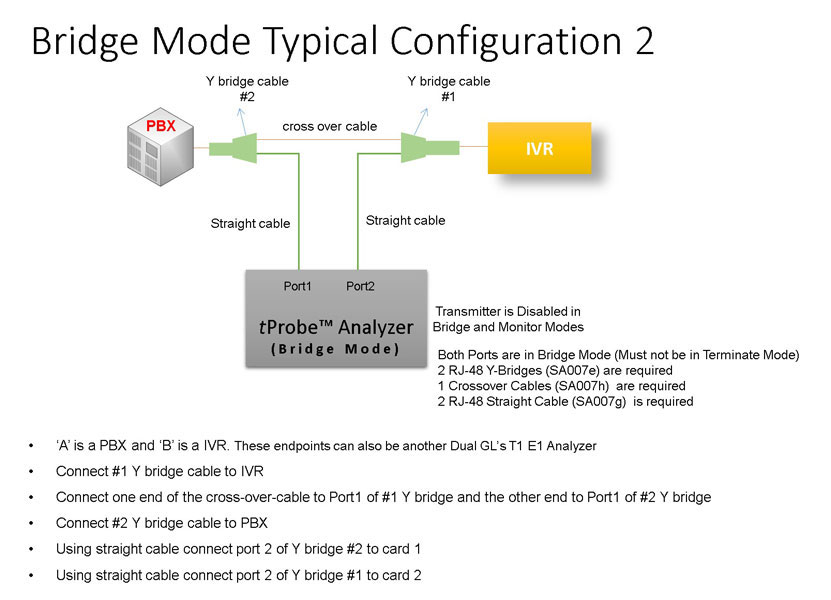
Bridge and Monitor Connections
- Monitor from a DSX-Patch Panel
- Bridge Mode Connections for Monitoring T1 E1 Signals for RJ-45
- Bridge Mode Connections Alternative Method
- RJ-45 Connections
- RJ-45 Splitter connection method
Resources
Please Note: The XX in the Item No. refers to the hardware platform, listed at the bottom of the Buyer's Guide, which the software will be running on. Therefore, XX can either be ETA or EEA (Octal/Quad Boards), PTA or PEA (tProbe Units), XUT or XUE (Dual PCIe Express) depending upon the hardware.
| Item No. | Item Description |
| MFC-R2 Simulation Products | |
|---|---|
| XX651 | T1 or E1 MAPS™ CAS Protocol Emulator (Script Based) * |
| XX625 | T1 or E1 CAS Simulator (Client-Server Based) * |
| XX022 | DTMF/MF/MFR2 Detector and Generator Software |
| XX020 | Record and Playback of Files |
| XX051 | Synchronous Trunk Record Playback |
| *CAS Simulation over T1 or E1 requires additional software licenses | |
| XXX610 | Client Server w/ Tx-Rx File |
| XXX620 | Client Server w/ DTMF |
| XXX630 | Client Server w/ DSP Operations |
| MFC-R2 Analysis Products | |
| XX031 | Enhanced T1 E1 Call Capture/Analysis Software |
| CCA Cable Kit | 2 -SA007e Y Bridges, 1 - SA017a & 1 - SA017b Straight & Crossover Cables, & 1 - SA007k Mono to Stereo Miniature Phone Y Cable Goldwave Software (SA048) |
| XX024 | Real-Time Strip Chart |
| XX050 | Signaling Bits Recorder |
| Other Related Software | |
| SA026 | Adobe Audition Software |
| SA048 | Goldwave Software |
| SA021 | File Edit Software |
| VBA032 | Near Real-time Voice-band Analyzer |
| PKV104 | FaxScan™ for SIP and Fax over IP (T.38) |
| Related Hardware | |
| XTE001 |
Dual T1 E1 Express (PCIe) Boards (requires additional licenses) |
| FTE001 ETE001 ETA001 EEA001 |
QuadXpress T1 E1 Main Board (Quad Port– requires additional licenses) OctalXpress T1 E1 Main Board plus Daughter Board (Octal Port– requires additional licenses) Basic Software for T1 (includes xx600, xx605) (zero dollar, but required with appropriate licenses) Basic Software for E1 (includes xx600, xx605) (zero dollar, but required with appropriate licenses) |
| PTE001 |
tProbe™ T1 E1 Base Unit |