MAPS™ GSM A Interface Emulator
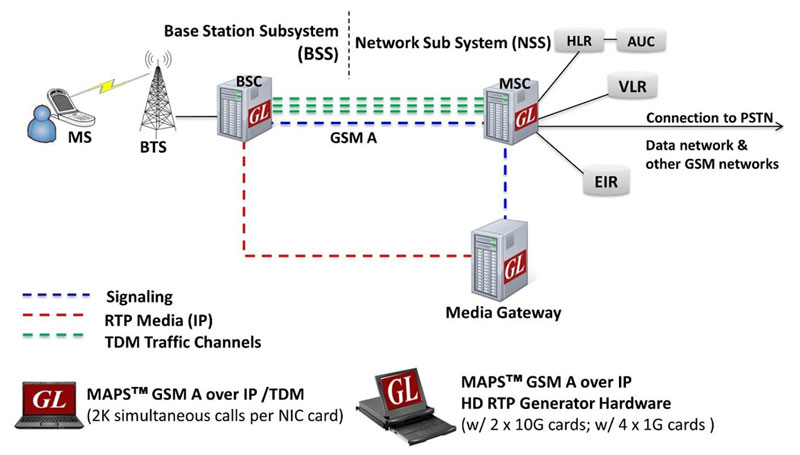
Simulation of GSM A interface connecting MSC and BSC network elements supporting high volume of TDM and RTP Media (IP) traffic.
GSM A - Brochure GSM A - IP BrochureRequest a Demo / Quote
Background
GSM is a globally accepted standard for digital cellular communications. GSM stands for Global System for Mobile Communication and is an open, digital cellular technology used for transmitting mobile voice and data services. A GSM network is made up of multiple functional entities and interfaces that facilitate sending and receiving of signaling and traffic messages. It is a collection of transceivers, controllers, switches, routers, and registers.
The GSM network can be divided into following broad parts.
- The Mobile Station (MS)
- The Base Station Subsystem (BSS)
- The Network Switching Subsystem (NSS)
- The Operation Support Subsystem (OSS)
The MS and the BSS communicate across the Um interface, also known as the air interface or radio link. BTS and BSC will communicate across A-bis interface and The BSS communicates with the Network Service Switching center across the A interface.
At the MSC, the information is mapped across the A interface to the MTP Layers 1 through 3 from the BSC. Here the equivalent set of radio resources is called the BSS MAP. The BSS MAP/DTAP and the MM and CM are at the upper layers of Layer 3 protocols. This completes the relay process. Through the control-signaling network, the MSCs interact to locate and connect to users throughout the network. Location registers are included in the MSC databases to assist in the role of determining how and whether connections are to be made to roaming users.
Overview
GL’s MAPS™ GSM A Interface Emulator is an advanced protocol simulator/tester for GSM simulation over A Interface that can simulate MSC and BSC network elements for exchanging BSSMAP and DTAP messages as defined by 3GPP standards. The tester supports Error tracking, regression testing, conformance testing, load testing/call generation and generation of high volumes of GSM traffic over TDM as well as IP interface. It is able to run pre-defined test scenarios against GSM A interface test objects in a controlled & deterministic manner.
MAPS™ GSM A over IP/TDM supports mobility management procedures over GSM A interface such as Location Management Procedure, Mobile Originating and Terminating Procedures, and Handover Management Procedures. It supports send/receive SMS simultaneously using signaling channel with the voice/data/fax services over a GSM network.
GSM A Interface Emulator supports powerful utilities like Message Editor, Script Editor and Profile Editor which allow custom call scenarios to be created or existing scenarios to be modified.
With the purchase of RTP Core license (PKS102), MAPS™ GSM A supports transmission and detection of various RTP traffic such as, digits, voice file, single tone, dual tones, IVR, User-defined traffic, FAX*, Video*, and VQT*. With regular RTP traffic, the maximum Simultaneous Calls up to 2500, and Calls per Second up to 250 is achievable. Almost all industry standard voice codec are supported.
With the purchase of TDM traffic licenses (xx610, xx620, xxFT0) GSM traffic can be simulated over T1 E1 interfaces. Supported traffic includes transmission and detection of digits, voice files, single tone, dual tones, FAX, Dynamic VF, User defined Traffic, IVR, and VQT.
By mimicking real-world customer behavior in lab environments, our solutions allow mobile operators and equipment manufacturers to verify their wireless networks before deployment. In other words, one can setup a virtual real-time network simulating all the network elements using “2G and 2.5G GSM GPRS Communications Network Lab Suite”. The test suite supports simulation of GSM Abis, GSM A, C/D/E, Gb, and GnGp interfaces.
MAPS™ GSM A IP is also available in High Density version(requires a special purpose network appliance and PKS109 RTP HD licenses). This is capable of high call intensity (hundreds of calls/sec) and high volume of sustained calls (tens of thousands of simultaneous calls/platform).
** Some of these traffic types require additional licenses – contact GL for more information
Main Features
- Simulate BSC or MSC nodes
- Complete GSM A signaling simulation over IP along with RTP traffic
- Call simulation over single or multiple T1 E1 timeslots along with high volume automated traffic
- Supports transmission and detection of RTP/TDM traffic – Auto digits, voice file, single /dual tones, Fax, IVR, and User defined traffic
- Access to all BSSMAP and DTAP message parameters like TMSI, IMSI, CIC, MCC, LAC, and more
- User controlled access to optional parameters such as timers
- Supports Authentication, TMSI Reallocation, Encryption, and other optional procedures
- Ready scripts for Call Control, Mobility Management - Mobile Originating, Mobile Terminating, Location Updating procedures, Radio Resource Management, Mobile Originating and Terminating SMS, and Handover Management procedures
- Auto packet impairment with Latency, Packet Effects, and Packet Loss
- Supported codec types include G.711, G.729, G.726, GSM, AMR, EVRC, SMV, iLBC, SPEEX, G.722, and more. *AMR, EVRC variants requires additional licenses.
- User-friendly GUI for configuring the SCTP/TCP and MTP Layers
- HD appliance supports high density call simulation of up to 20,000 calls with traffic (5000 calls per port) – Requires additional hardware and licenses
- Setup a virtual real-time GSM network simulating all the network elements using ‘2G and 2.5G GSM GPRS Communications Network Lab Suite’
- Multiple UE related information can be accessed directly from Database, CSV files, or through regular XML Profiles for bulk call generation
- CSV or Database based profiles support massive number of UE records, and also support SMS calls ratio option to dynamically control the ratio of SMS and Voice calls to be generated
- Supports user defined graphs and statistics for monitoring performance of Signaling and RTP traffic
- Export call statistics PDF and XML file format report generation
- Customization of traffic parameters to be calculated and displayed for voice quality metrics such as Listening MOS, Conversational MOS, Packet Loss, Discarded Packets, Out of Sequence Packets, Duplicate Packets, Delay and Jitter
- Multi homing with multiple IP address configuration for single node is supported to keep the SCTP link continuously active between the connected nodes.
Supported Protocols Standards
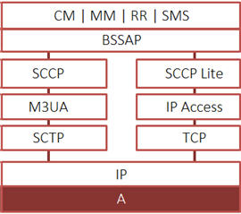 GSM A IP Interface Protocol Standards |
|
|||||||||||||||||||
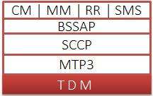 GSM A TDM Interface Protocol Standards |
|
|||||||||||||||
Location Updating Call Procedure
LUC Procedure
LUC Generation and Reception
The MAPS™ GSM A can also act as Base Station Controller (BSC) initiating the Location Updating Call procedure by sending Location Updating Request to the Network (MSC). The DUT on receipt of a LOCATION UPDATING REQUEST message sends a CC connection confirm message in response as shown in the figure below. Also, simulates the complete call flow as in typical Location Updating Call (MOC) procedure.
LUC Call Generation
LUC Call Reception
Mobile Originating Call Procedure
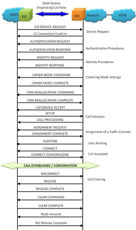
MOC Procedure
MOC Generation and Reception
MAPS™ GSM A acts as Base Station Controller (BSC) and initiates the Mobile Originating Call procedure by sending CM Service Request to the DUT (MSC). The DUT on receipt of a CM SERVICE REQUEST message should send a CC connection confirm message in response as shown in the figure below. Also, simulates the complete call flow as in typical Mobile Originating Call (MOC) procedure.
MOC Call Generation
MOC Call Reception
Mobile Terminating Call Procedure
MTC Procedure
MTC Generation and Reception
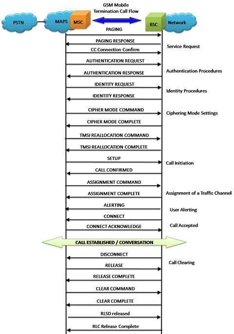
MAPS™ GSM A acts as Mobile Station Controller (MSC) processing the call flow by initiating the Paging message to from the Mobile Station (BSC). The DUT (BSC) on receipt of a Paging message, sends a Paging Response message back to MSC. Also, simulates the complete call flow as in typical Mobile Terminating Call (MTC) procedure.

MTC Call Generation
MTC Call Reception
Handover Management Procedure
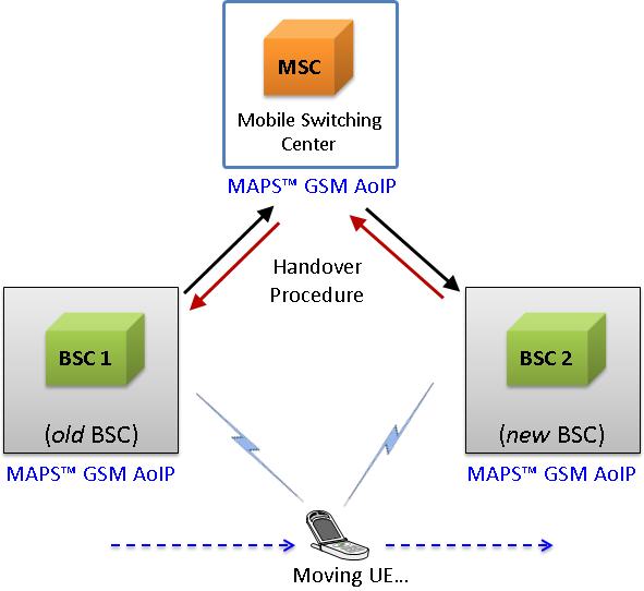
When a mobile user travels across two different cell coverage areas within an active call duration, the call is transferred to the new cell’s base station. When the user is travelling across two different cell coverage areas, the Handover procedures are initiated from old BSC to new BSC via MSC. These procedures can be simulated using MAPS™ GSMA over IP Emulator.
Handover Management Procedure
The following diagram depicts the typical end-to-end call flow between the entities during the Handover procedure:
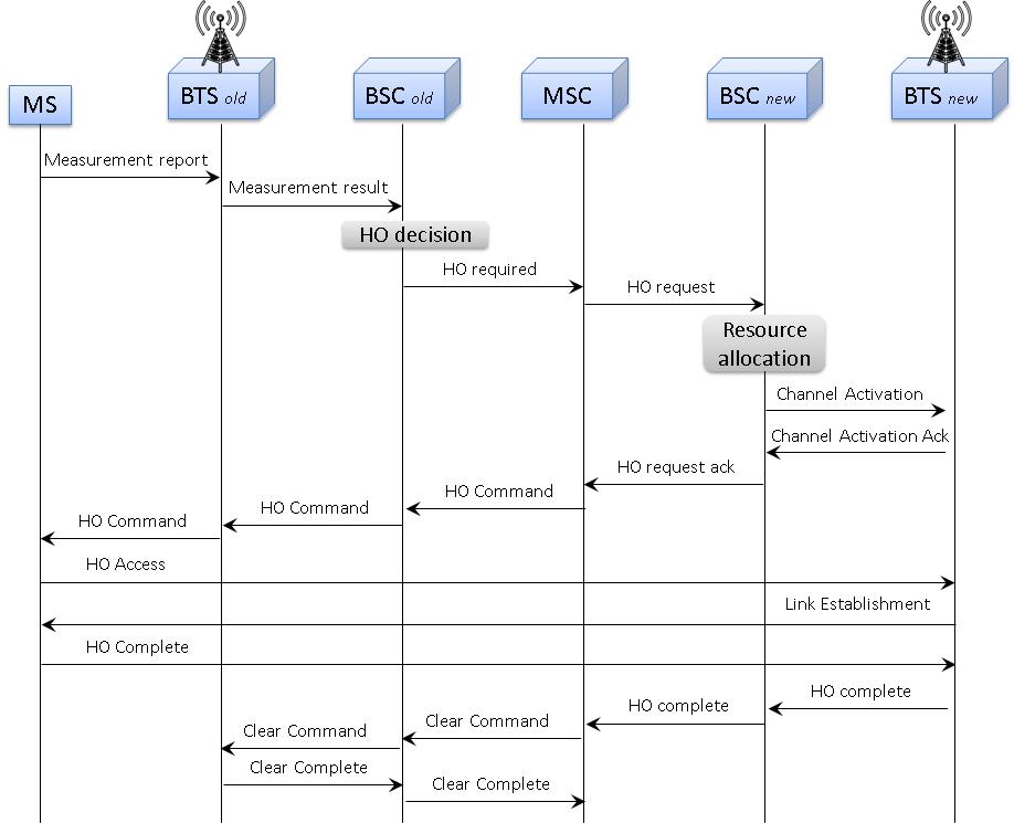
Typical Handover Management Call Procedure
The following screenshot depicts the end-to-end Handover call flow between the old BSC and new BSC via MSC simulated using MAPS™ GSMA over IP Emulator.
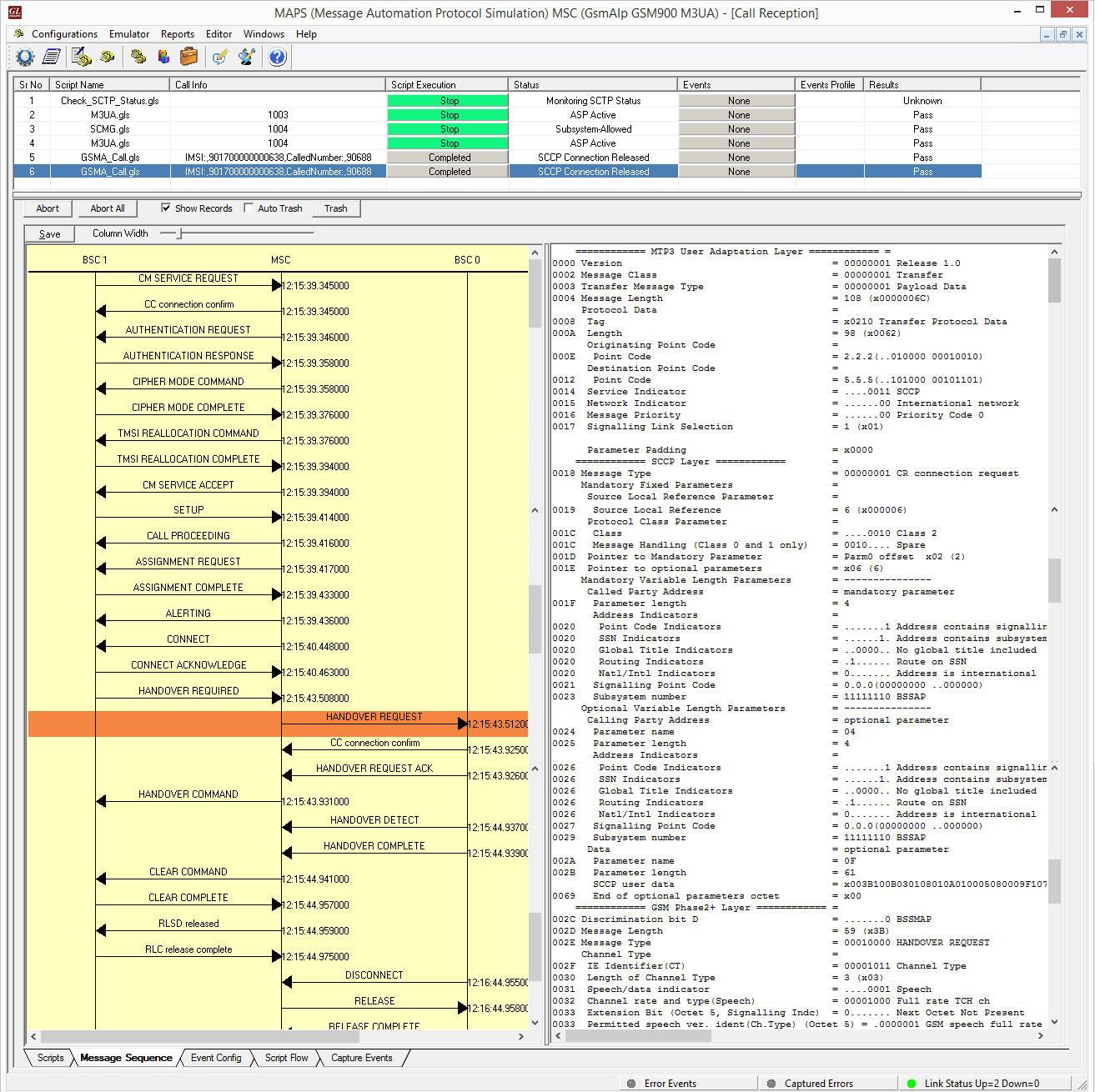
Handover Management Procedure Simulation using MAPS™
SMS Call Procedure
Short Message Service (SMS) is a mechanism of short messages delivery over the mobile networks. It is a store and forward way of transmitting messages to and from mobile phones. The messages (text only) from the sending mobile is stored in a central short message Center (SMC) which then is forwarded to the destination mobile.
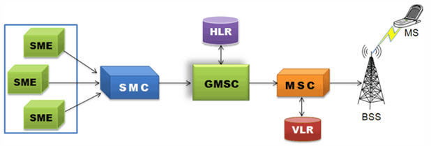
SMS Network
The following diagram depicts the typical SMS call procedure
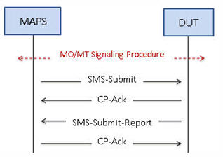
SMS Call Procedure
Mobile Originating SMS Call Generation and Reception
MAPS™ GSM A acts as Base Station Controller (BSC) and initiates the Mobile Originating Call procedure by sending CM Service Request to the DUT (MSC). The DUT on receipt of a CM SERVICE REQUEST message should send a SMS SUBMIT message in response as shown in the figure below. Also, simulates the complete call flow as in typical Mobile Originating SMS Call (MOC) procedure.
|
|
Mobile Terminating SMS Call Generation and Reception
MAPS™ GSM A acts as Mobile Station Controller (MSC) processing the call flow by initiating the Paging message to from the Mobile Station (BSC). The DUT (BSC) on receipt of a Paging message, sends a Paging Response message back to MSC. Also, simulates the complete call flow as in typical Mobile Terminating Call (MTC) procedure.
|
|
Bulk UE Simulation with CSV based Profiles
In real time scenario, there exists huge number of subscribers with unique UE parameters. MAPS™ supports bulk call generation to stress and load test the network with number of subscriber profiles. Each profile can have unique parameters to simulate different real-time scenarios. However, creating and maintaining massive number of XML based subscriber profiles with unique mobile identifiers such as IMSI, TMSI, MSISDN and traffic parameters is not feasible. Therefore, recent enhancements were introduced to MAPS™ GSMA over IP test tools to include CSV subscriber profiles. CSV database system used within MAPS™ is a simple Excel® file that can dynamically generate up to 20,000 number of subscribers with unique identifiers (IMSI, TMSI, MSISDN) and other key parameters in sequential order.
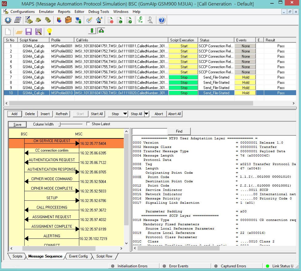
Bulk Call Generation with CSV based Subscriber Profiles
MAPS™ also includes option to configure the ratio of SMS calls out of Total number of Calls. Considering 100% Total Calls, MAPS™ will generate SMS calls and MO Voice calls as per the defined ratio. For example, if the configured SMS call Ratio = 30% in Testbed, then during bulk call simulation, MAPS™ generates 30% SMS calls and remaining 70% of total calls generated will be MO Voice calls.
The call generation is based on the IMSI key parameter and call is received based on the Called Number key parameter. The Records are fetched from the CSV file for 2 different Key parameters, i.e., IMSI and CallingNumber. At MSC, 2 CSV files are saved in the working directory and is loaded in MAPS™. MS_Profiles_IMSI.csv file for key=IMSI, and MS_Profiles_CallingNumber.csv file for key=CallingNumber.
Sample MS_Profiles_IMSI.csv File
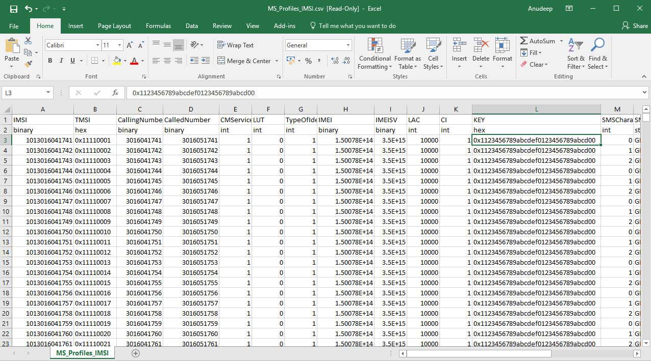
Supplementary Service Activation Call Flow
Supplementary Service (USSD) is a communication protocol used by cellular telephones to communicate with the computers of mobile network operator. This service can be used for WAP browsing, prepaid callback service, mobile-money services, location-based content services, menu-based information services, and as part of configuring the phone on the network.
Once the location update is successful, Supplementary Services procedure is initiated from the UE towards the network.
The following figure illustrates the Supplementary Service call flow between MAPS™- GSMA and DUT.
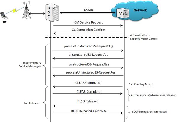
Supplementary Service Activation Call Generation and Reception
MAPS™ GSM A acts as Base Station Controller (BSC) and initiates the Mobile Originating Call procedure by sending CM Service Request to the DUT (MSC). The DUT on receipt of a CM SERVICE REQUEST message should send a CC connection confirm message in response as shown in the figure below. The processUnstructredSS-Request message is sent from BSC to MSC to start the supplementary call service. Also, simulates the complete call flow as in typical Supplementary Service Activation Call procedure.
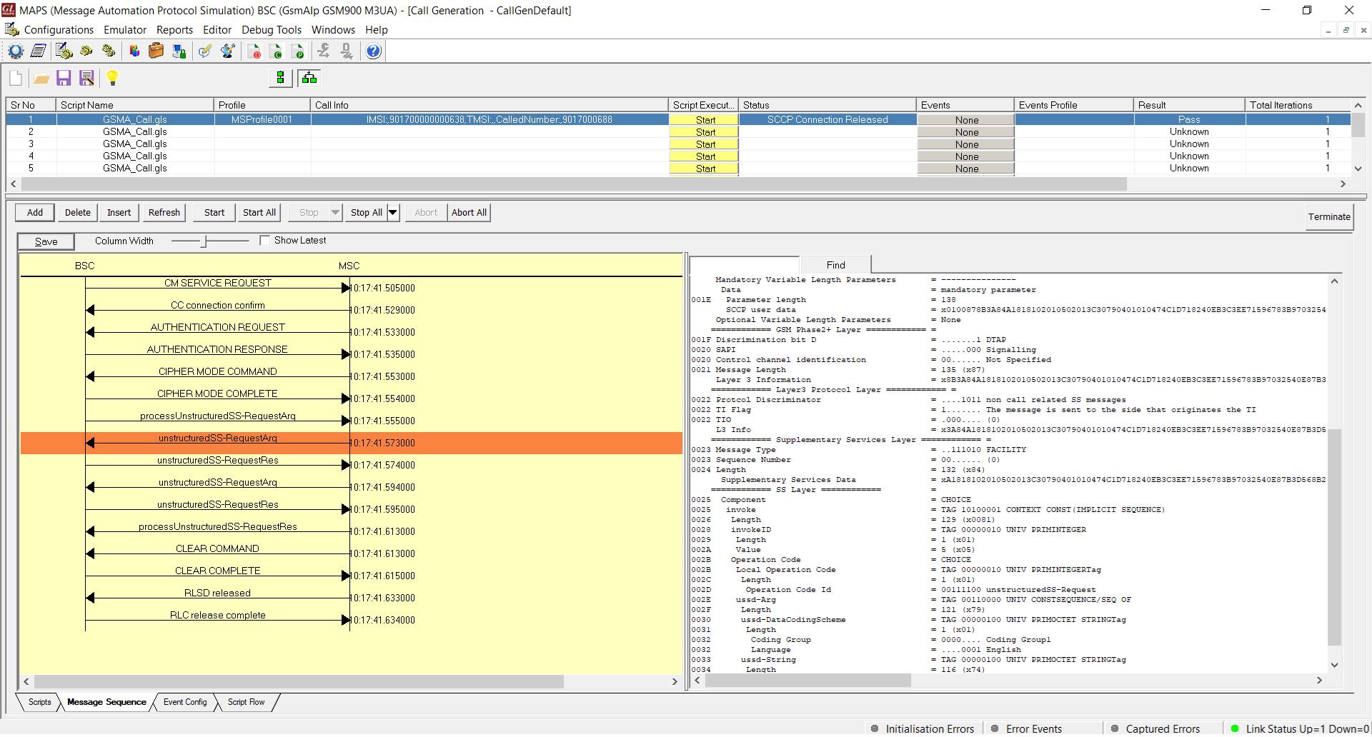
Supplementary Service Activation Call Generation
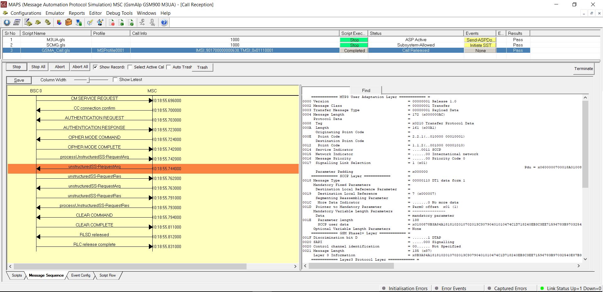
Supplementary Service Activation Call Reception
Resources
Please Note: The XX in the Item No. refers to the hardware platform, listed at the bottom of the Buyer's Guide, which the software will be running on. Therefore, XX can either be ETA or EEA (Octal/Quad Boards), PTA or PEA (tProbe Units), XUT or XUE (Dual PCIe Express) depending upon the hardware.