MAPS™ MAP Emulator
Simulation of all the GSM (C, D, E, F) and UMTS (Gc, Gd, Gf, Gr) MAP (Mobile Application Part) interfaces over both TDM, ATM and IP networks.
Brochure Request a Demo / Quote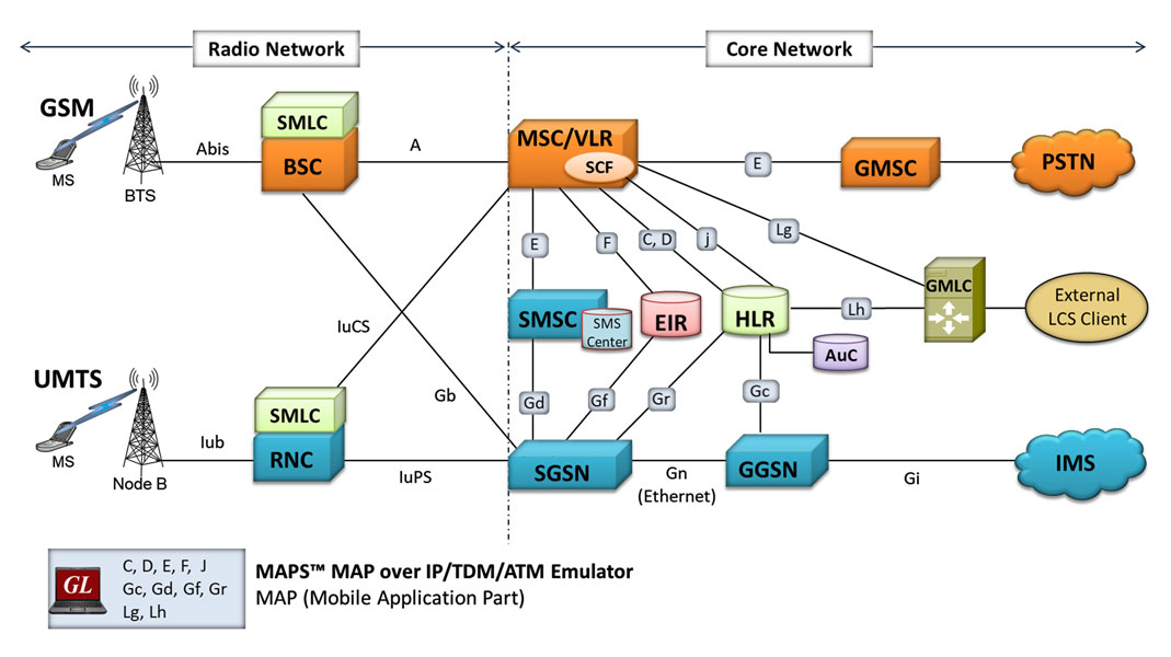
Background
Mobile Application Part (MAP) is an application layer protocol used by various elements in GSM, UMTS, and GPRS mobile core networks to provide services to mobile phone users.
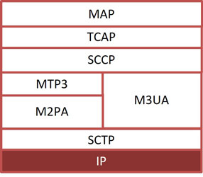
MAP can be transported using 'traditional' SS7 protocols in TDM/ATM (T1 and E1) or over IP using SIGTRAN.
SIGTRAN is a stack of networking protocols having Stream Control Transport Protocol (SCTP) for stream management over IP, and a bunch of user adaptation (UA) layers over it. Supported adaptation layers are M2PA (MTP2 Peer-to-Peer), M3UA (MTP 3 User), and M2UA (MTP2 User).
As illustrated in the diagram above, some of the GSM/UMTS circuit switched interfaces such as C (between HLR & MSC), D (between HLR and VLR), E (between GMSC and MSC), F (between MSC and EIR), H (between HLR and AuC) and Packet-switched interfaces such as Gc (between GGSN and HLR), Gr (between SGSN and HLR), Gf (SGSN and EIR), Gd (between SGSN & SMS-GMSC) use Mobile Application Part (MAP) protocol.
MAP over IP network also includes LCS (Location Services) specific elements and entities, their functionalities, interfaces, as well as communication messages, necessary to implement the positioning functionality in a cellular network. Location Services (LCS) architecture follows a client/server model with the gateway mobile location Center (GMLC) acting as the server providing information to External LCS Clients.
The "radio" and "core" network partition is shown above for GSM and UMTS networks. Elements and interfaces that comprise the core network are briefly described below.
Common services provided by MAP are “Location Services”, "Location Tracking", "Roaming", "Subscription Information", "Short Message Service", and many more.
| Interface | Elements | Purpose | TDM/ATM (T1 E1) |
IP |
|---|---|---|---|---|
B |
MSC-VLR |
Generally an internal interface within the MSC. Used whenever the MSC needs access to data regarding a MS located in its area. |
||
C |
MSC-HLR |
MSC server interrogates the HLR for routing information of a subscriber for a call or SMS directed to that subscriber |
||
D |
VLR-HLR |
Used to exchange data related to the current location of a mobile station and to the management of that subscriber |
||
E |
MSC-GMSC |
Exchange of handover data between two adjacent MSCs for the purpose of seamless call and message flow |
||
F |
MSC-EIR |
Used by the EIR to verify the status of the IMEI retrieved from the Mobile Station |
||
G |
VLR-VLR |
Used to update a new VLR with IMSI and authentication info from old VLR, when a mobile subscriber moves from one VLR area to another (not shown in the diagram) |
||
H |
HLR-AuC |
HLR requests for authentication and ciphering data from the AuC for a Mobile Subscriber. |
||
Gc |
GGSN-HLR |
Used by the GGSN to retrieve information about the location and supported services for a mobile subscriber for packet data services (GPRS, etc.) |
||
Gr |
SGSN-HLR |
Used to exchange data related to the current location and management of a Mobile Subscriber (MS) and Mobile Equipment (ME) |
||
Gf |
SGSN-EIR |
Used by the EIR to verify the status of the IMEI retrieved from the Mobile Station. |
||
Gd |
SGSN-SMSC |
Used to transfer SMS over GPRS. |
||
Lg |
MSC |
Used in Location Services between MSC and GMLC to provide subscriber location and related report |
||
Lh |
GMLC |
Used in Location Services between the GMLC and the HLR to retrieve the routing information needed for routing a location service request to the servicing VMSC, SGSN, MME or 3GPP AAA server |
Overview
GL's MAPS™ (Message Automation & Protocol Simulation) product line bearing the same acronym, is used to emulate all the MAP interfaces listed above – both TDM, ATM and IP.
MAPS™ is an advanced and versatile protocol simulator/tester that can simulate a variety of protocols encountered in the telecom space, including SIP, MGCP, UMTS, GSM, MLPPP, MEGACO, ISDN, CAS, SS7, and many more. MAPS™ MAP supports emulation of all the GSM and UMTS MAP interfaces. MAPS™ MAP currently supports various procedures emulating MSC (VLR), HLR, EIR, and SMSC entities and H, C, D, E, F interfaces in the network. Supported procedures include Location Update, Retrieve Roaming Number, Remote User Status, Check IMEI Service, and others. The product also supports send/receive SMS (Short Message Service) simultaneously using signaling channel with the voice/data/fax service over GSM network.
MAPS™ MAP is enhanced to simulate Location Services (LCS) over Lg and Lh interfaces connecting GMLC <-> MSC and GMLC <-> HLR entities. Supported LCS procedures includes Provide Subscriber Location, Subscriber Location Report, and Routing Info for LCS respectively, as per 3GPP TS 23.271 specifications.
In addition to supporting MAP network elements connected by the interfaces listed, it also supports error tracking, regression testing, conformance testing, load testing, and call generation. It can run pre-defined test scenarios against test objects in a controlled & deterministic manner.
MAPS™ MAP Emulator supports powerful utilities like Message Editor, Script Editor, and Profile Editor which allow new scenarios to be created or existing scenarios to be modified using MTP3 layer (over TDM/ATM) and M3UA, M2PA layers (over IP) messages and parameters.
MAPS™ MAP ATM uses SSCOP server for establishing SSCOP links over which MAP signaling will be carried further for making calls. SSCOP Server is GL's WCS based server module and provides SSCOP, and AAL5 layer services.
Over successfully established call, traffic can be generated. MAPS™ MAP ATM internally uses AAL5 Traffic Generator for traffic generation. Various traffic types like Tone, Digits and File playback are supported.
The AAL5 traffic simulation supports the following actions:
- Transmitting Voice Files
- Transmitting DTMF, MF Digits, and other Tones and Dual Tones
- Recording Voice Files
- Monitoring Single and Dual Tones, DTMF, and MF digits
MAPS™ supports Command Line Interface (CLI) and when configured as server-side application enables remote controlling of the application through multiple command-line based clients including Python, Java, TCL and others, using MAPS™ client-server architecture (requires additional license).
GL also provides various set of protocol analyzers for on-line capture and decode of the signaling in real-time both during tests and as a stand-alone tracer for live systems. Please visit Protocol Analysis page for more details.
Testing Features
- MAP protocol simulation over TDM and ATM (T1 E1)
- Emulator can be configured as MSC (VLR), HLR, GMSC, EIR, SMSC, SGSN, and GGSN entities and emulate C, D, E, F interfaces in the GSM network and Gc, Gd, Gf, and Gr in the UMTS network.
- User-friendly GUI for configuring the MAP signaling links
- Access to all MTP3, SCCP, and MAP R4 protocol fields such as TMSI, IMSI, MCC, MNC, MSIN, CCBS and more
- Ready scripts for GPRS Update procedure, Mobile Originating (MO) SMS, Mobile Terminating (MT) SMS, Location Update, Authentication, Retrieval of Routing Information Procedure, Check IMEI Status (Equipment Identification), and Unstructured Supplementary Service Data (USSD) procedures.
- Logging of all messages in real-time
- Supports customization of placing and answering calls using Profile editor and Message editor
- Ready-to-use scripts for quick testing
- Provides protocol trace with full message decoding of the GSM messages
- Provides call reports with associated captured events and error events during call simulation
- Option to send reports to database accessible via web interface
- MAP is enhanced to simulate Location Services (LCS) over Lg and Lh interfaces
Supported Protocols Standards
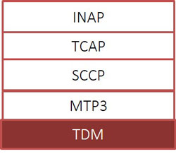
Protocol Stack TDM 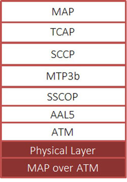
Protocol Stack ATM |
|
||||||||||||||||||||||||||||||
 |
|
||||||||||||||||||
MAP C, D Interface
Shown below are the typical MAP procedure over IP and TDM, ATM interfaces:
MAP/D Mobile Originating Call Flow
MAP/D Location Update Call Flow
MAP/C, MAP/D Retrieval Routing Information Call Flow

Remote User Status Procedure
Call Generation and Reception
MAPS™ is configured as MSC/VLR which initiates the LocationUpdate procedure by sending the updateLocationArg message to HLR. MAP_UPDATE_LOCATION service is used by the VLR to update the location information stored in the HLR. This is performed using the UpdateLocationArg_MSCVLR.gls script.
MAP Call Generation at MSC/VLR Node
MAPS™ can also be configured as HLR which receives the request message from MSC and simulates complete LocationUpdate procedure.
MAP Call Reception at HLR Node
MAP E Interface
Shown below are the typical MAP E interface procedures between MSC and SMSC over IP and TDM, ATM interfaces:
Mobile Terminating (MT) and
Mobile Originating (MO) SMS Procedures
Call Generation and Reception
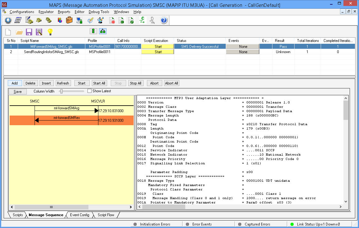
MAPS™ is configured as SMSC which initiates the Mobile Terminating SM procedure by sending the mtforwardSMArg message to MSC.
This service is used to forward mobile terminated short messages between SMSC<--->MSC.
This is performed using the MtForwardSMArg_SMSC.gls script. This Script Initiates Mt Forward SMS Message and waits for Mt forward SMS Response.
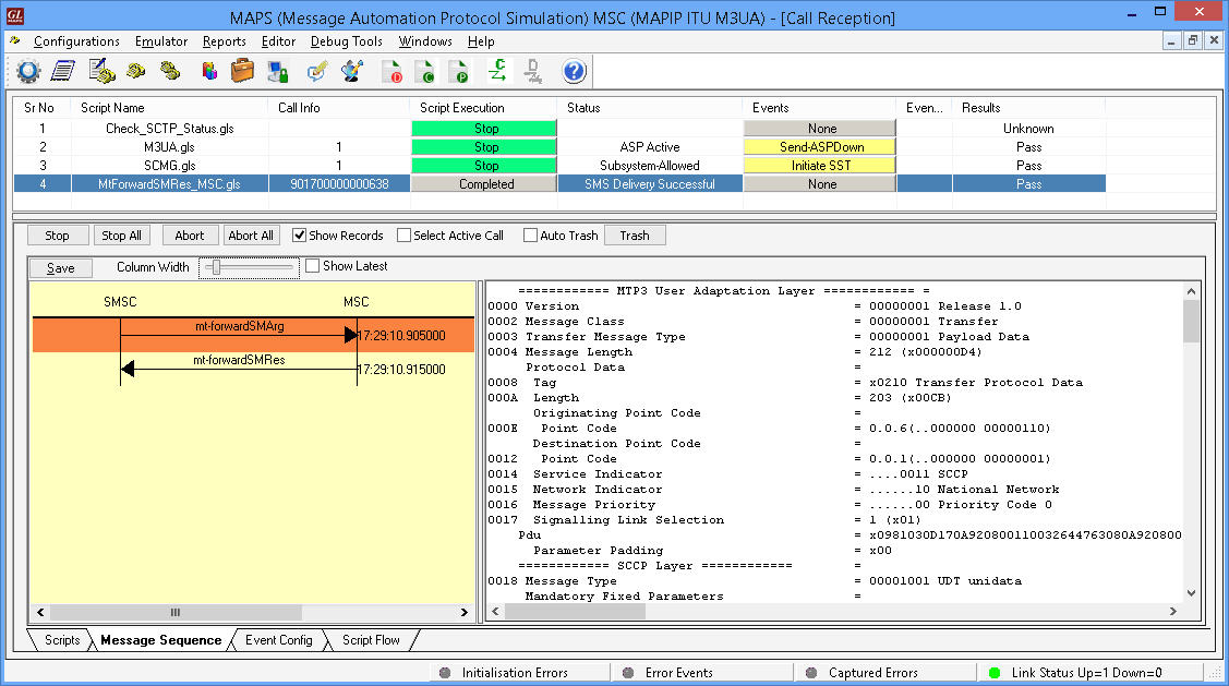
MAPS™ can also be configured as MSC which receives the request message from SMSC and simulates complete Mobile Terminating SM procedure.
MAP F Interface
Shown below are the typical MAP F interface procedures between MSC and EIR over IP and TDM, ATM interfaces:
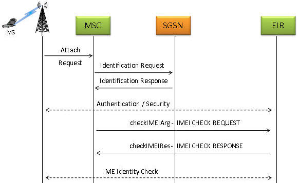
Check IMEI Status Procedure
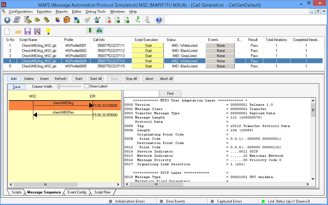
Call Generation and Reception
MAPS™ is configured as MSC which initiates the MAP_CHECK_IMEI service by sending the checkIMEIArg message to EIR.
This service is used between MSC and the EIR to get the IMEI status of the Subscriber. If the IMEI is not available in the MSC or in the SGSN, it is requested from the MS and transferred to the EIR in the service request.
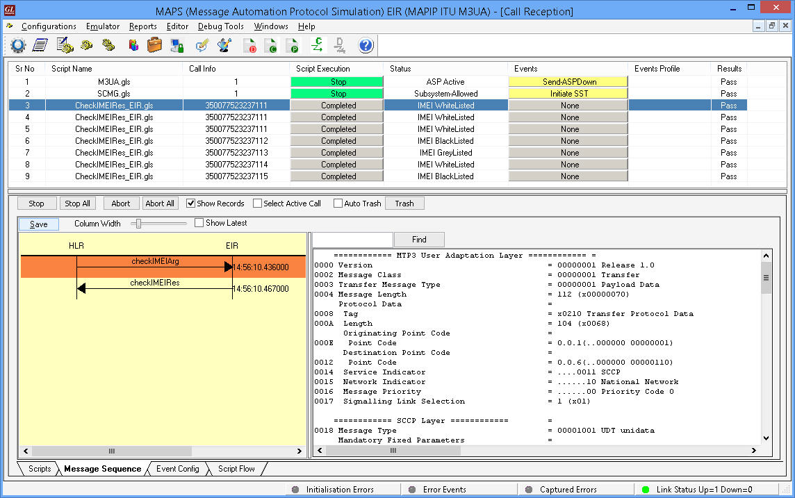
MAPS™ can also be configured as EIR which receives the request message from MSC and simulates complete MAP_CHECK_IMEI procedure.
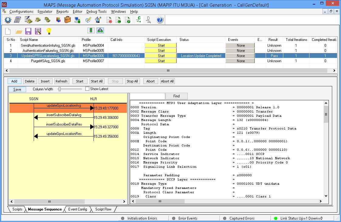
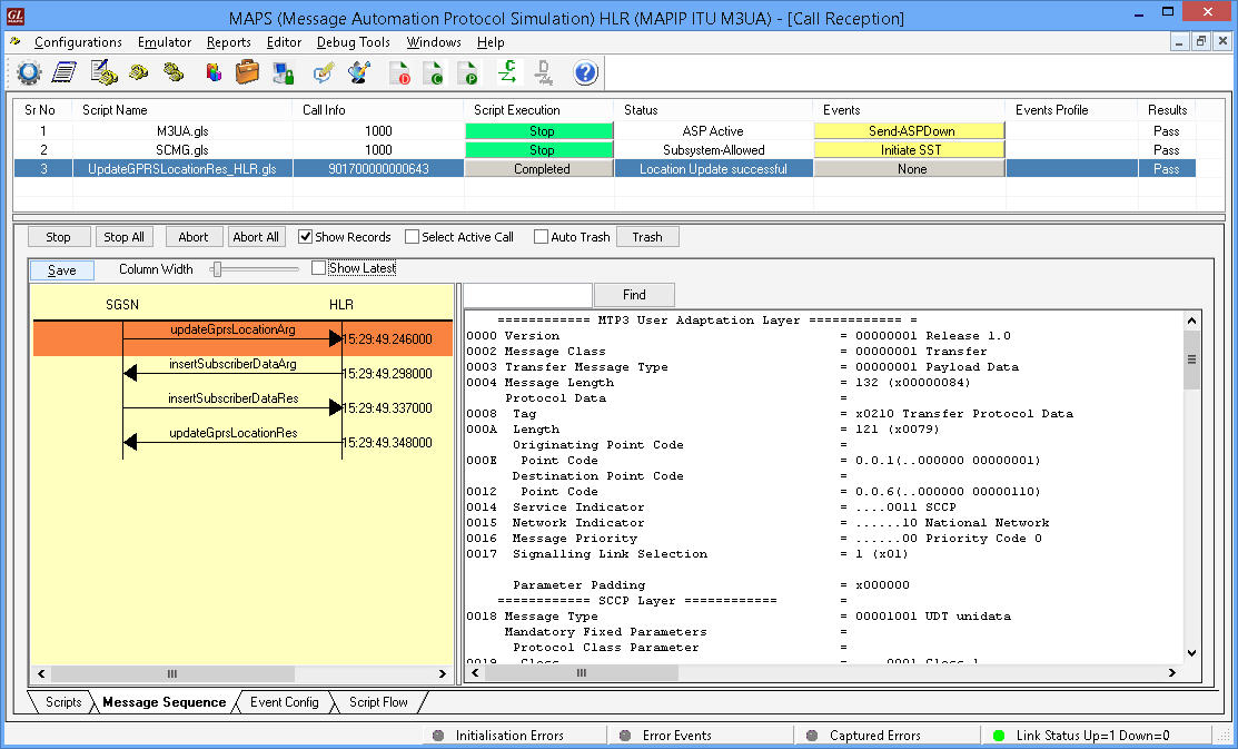
MAP Gr Interface
Shown below are the typical MAP Gr interface procedures between SGSN and HLR over IP and TDM, ATM interfaces:

GPRS Location Update Procedure
Call Generation and Reception
MAPS™ is configured as SGSN which initiates the MAP-UPDATE-GPRS-LOCATION service by sending the updateGprslocationArg message to HLR.
This location updating procedure is used to update the location information stored in the HLR. This service is invoked towards the HLR whose identity is contained in the SGSN. This is performed using the UpdateGPRSLocationArg_SGSN.gls script
MAPS™ can also be configured as HLR which receives the request message from SGSN and simulates complete MAP-UPDATE-GPRS-LOCATION procedure.
LCS Lg, Lh Interfaces
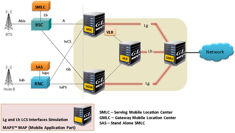
Location Service (LCS) Architecture
MAPS™ MAP supports both server and client simulation for the Mobile Application Part (MAP) Lg, and Lh interfaces. MAPS™ can be configured as GMLC testing SGSN/MSC in UMTS network and vice-versa.
Location based services, such as Emergency Services, rely upon Location Service (LCS). The Lg and Lh interfaces enable LCS in the GPRS/UMTS to provide support for specialized mobile location services for operators, subscribers, and third party service providers.
MS initiated Location Report Procedure is supported over Lg Interface between GMLC and MSC and Network Initiated Location Retrieval Procedure over Lh Interface between GMLC and HLR.
The Lg interface implements the following Mobile Application Services:
- MAP-Provide-Subscriber-Location - used by a GMLC to request the location and optionally, velocity, of a target UE;
- MAP-Subscriber-Location-Report – used by a SGSN/MSC to provide the location of a target UE to a GMLC.
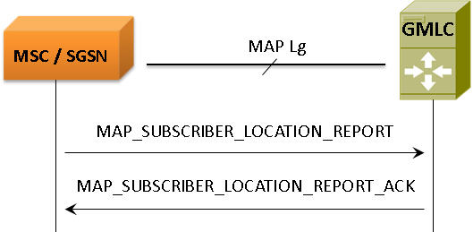
Lg Interface-LCS Procedure
The Lh interface implements the following Mobile Application Services:
- MAP-SEND-ROUTING-INFO-FOR-LCS, used by GMLC to retrieve the routing information from HLR, required to route a location service request to the serving VMSC, SGSN, MME or 3GPP AAA server.
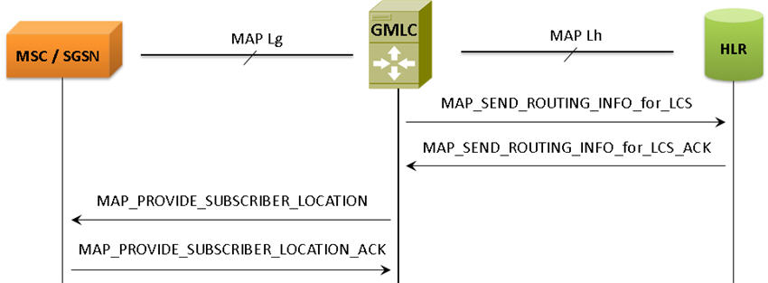
Network Initiated Location Retrieval Procedure
Lg Interface
MAPS™ MAP IP configured as GMLC initiates the PROVIDE-SUBSCRIBER-LOCATION Service by sending provideSubscriberLocationArg message requesting for the location of a target MS from the visited MSC or SGSN at any time.
Lh Interface
MAPS™ MAP IP configured as HLR receiving SEND-ROUTING-INFO-FOR-LCS Service request message from GMLC to retrieve the routing information needed for routing a location service request to the servicing VMSC, SGSN, MME or 3GPP AAA server.
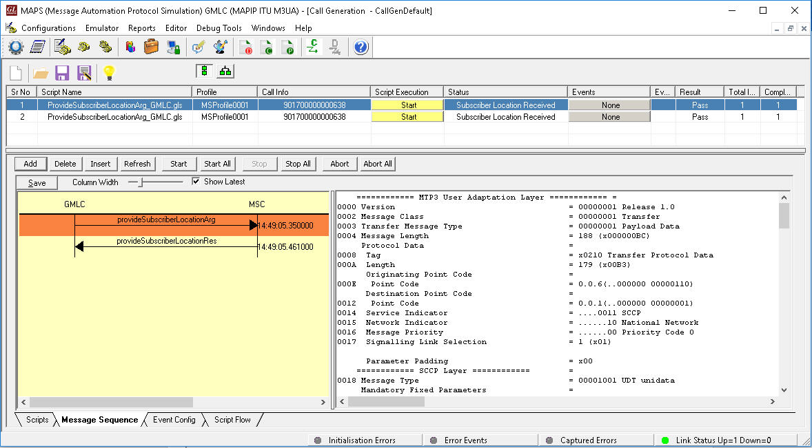
MAPS™ MAP IP (GMLC) Simulating Lg Interface Procedure
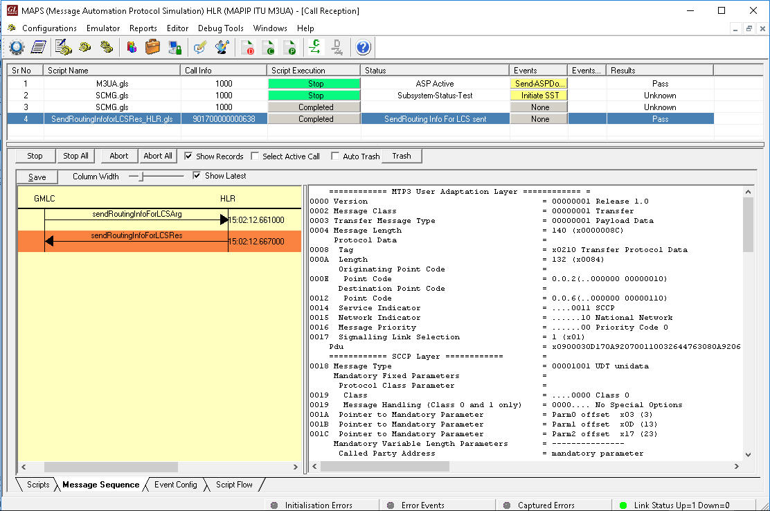
MAPS™ MAP IP (HLR) Simulating Lh Interface Procedure
Resources
Please Note: The XX in the Item No. refers to the hardware platform, listed at the bottom of the Buyer's Guide, which the software will be running on. Therefore, XX can either be ETA or EEA (Octal/Quad Boards), PTA or PEA (tProbe Units), XUT or XUE (Dual PCIe Express) depending upon the hardware.