Critical Delay Measurements in
Air Traffic Management
GL has developed MAPS™ Timing Measurements in Air Traffic Management test suite to accurately simulate end points in ATM network and provide critical timing measurements for various types of delay occurrences in signaling and voice transmission through the network.
Request a Demo / Quote Brochure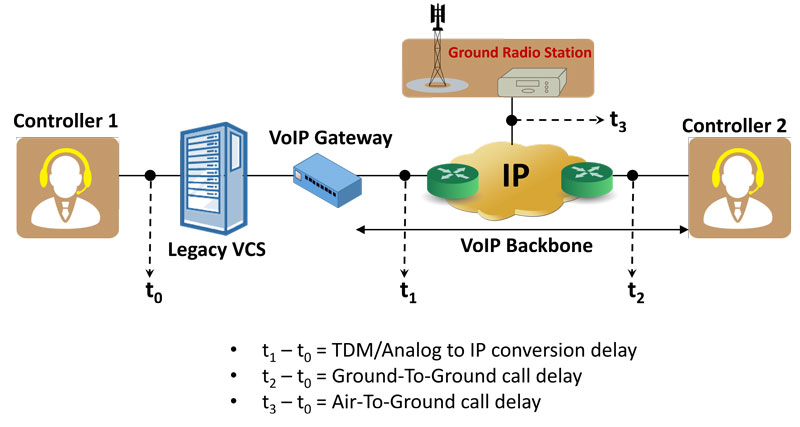
Overview
The latest EUROCAE (European Organization for Civil Aviation Equipment) ED-137 inter-operability standards, address migration and implementation of IP technology for voice services for air traffic control. The familiar industry standard SIP protocol is specified to establish, modify, and terminate voice sessions with endpoint equipment within an Air Traffic Services Ground Voice Network (AGVN).
As shown above, the endpoint equipment can be a SIP based Controller Working Position (CWPs), Next Generation Voice Communication Systems (VCS) and Radios, or VCS/Radio Gateways allowing interworking with older legacy equipment and protocols. The legacy TDM VCS system will initially connect to an IP WAN network backbone using VoIP gateways.
Though migrating to an IP network provides convergence advantages for traffic and interoperable network elements from various vendors, it also poses challenges – of variability of different implementations by equipment vendors. Some of these are: implementation of technologies with varied jitter buffer, packetization, digital signal processing algorithms, VOX operations, and switching from idle to active state. These implementation differences impact end-to-end delay requirements imposed by various industry standard bodies. Characterizing and limiting these impairments is critical to the performance of the system as a whole. Rigorous methods are needed to precisely measure the delay introduced by each network element as events propagate end-to-end. Recognizing, capturing, timestamping, and correlating events at analog, TDM and IP interfaces are necessary. Delay measurements should be conducted repeatedly to ensure that the device and network under test is performing as expected consistently over time.
GL's TM-ATM Solution for Timing Measurements
GL has developed MAPS™ TM-ATM (Timing Measurements in Air Traffic Management) test suite to accurately simulate end points in ATM network and provide critical timing measurements for various types of delay occurrences in signaling and voice transmission through the network. It includes all necessary hardware and software to identify, capture, timestamp, and correlate events at Analog, TDM and IP interfaces. The solution also supports all 4-wire and 2-wire legacy interfaces for comprehensive end-to-end timing and voice quality assessment.
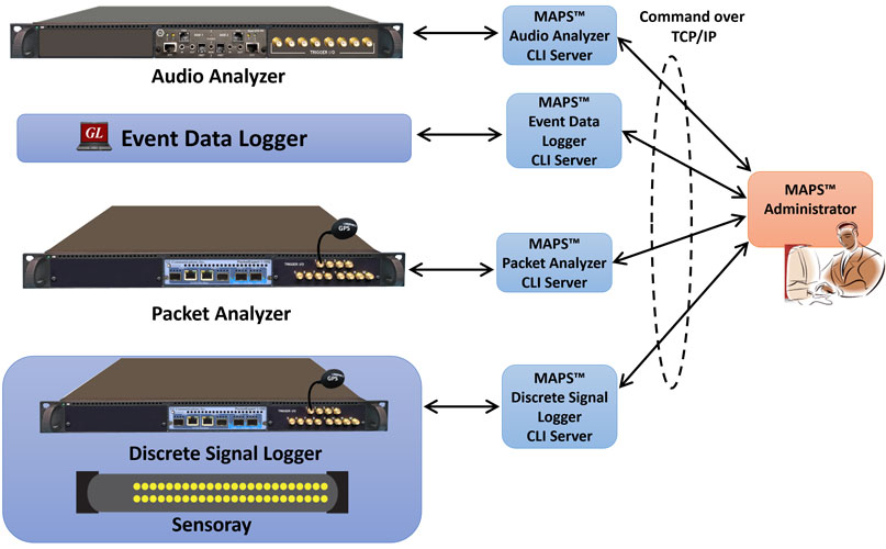
The above TM-ATM solution includes various GL test tools such as Audio Analyzer (which uses GL's VQuad™) and Packet Analyzer, Discrete Signal Logger (all these components use GL’s PacketExpert™- platform) and software based Event Data Logger. All these components are controlled by a centralized component called MAPS™ Administrator (TM-ATM Client). All the components support a client server model, with the MAPS™ Admin acting as a client and controlling all the other components which act as servers, from a centralized location.
Refer to Delay Measurements section for detailed information about the GL Test Tools used in the solution.
Critical Events and Measurements of Interest
Events of Interest as they propagate within Network:
- PTT Activation and Deactivation
- Squelch Enable and Disable
- Voice to/from CWP
- Voice to/from Radio
- Transition in RTP Payload
- Transition in RTP Headers
Network Delay measurements of interest:
- Transmitter activation delay
- Aircraft call indication delay
- Ground transmission voice delay
- Transmitter activation and aircraft call indication loopback delay
- Ground reception voice delay
- Ground transmission and reception voice loopback delay
- Frequency key activation response time and more
Some of the standards bodies like the Federal Aviation Administration (FAA) in the USA has published specification for NVS system defining timing requirements in detail. The below TABLE extracted (from the FAA-E-NVS1_NVS-Specification_v1_1_2012-01-10 document: refer Table 3-9) depicts Setup/Teardown Throughput Timing Requirements during Peak Busy Hour (PBH) and Peak Busy Minute (PBM).
Type of Event |
Max. Response Time, msec1,2 Percent of |
||
|---|---|---|---|
95% |
99.9% |
99.99% |
|
A/G Functions within the AVN |
|
|
|
System-Generated A/G PTT Transmit (radio cross coupling) |
40 |
|
45 |
Frequency Select |
125 |
175 |
|
Frequency Deselect |
125 |
175 |
|
Frequency cross couple Selection |
125 |
175 |
|
Frequency cross couple Deselection |
125 |
175 |
|
Frequency Preemption Activation |
25 |
|
30 |
PTT Lockout (Preemption) Busy Tone |
60 |
85 |
|
Frequency Site Selection |
125 |
175 |
|
Frequency Site Confirmation |
125 |
175 |
|
Local Receive Mute |
50 |
75 |
|
Local Receive Mute Indicator |
75 |
100 |
|
Local Receive Unmute |
50 |
75 |
|
Local Receive Unmute Indicator |
75 |
100 |
|
Also shown below, are timing requirements extracted from Eurocae standards document: (ED-136 - VoIP ATM System Operational and Technical Requirements Final Draft 2.0_Oct2008 refer Figures below)
To perform these timing measurements, one can setup MAPS™ TM-ATM ( Timing Measurements in Air Traffic Management) tools at appropriate strategic interfaces. GL’s MAPS™ TM-ATM is a custom suite of test tools, designed to accurately measure various types of delay occurrence in signaling and voice transmission. It includes all necessary hardware and software to identify, capture, timestamp, and correlate events at Analog, TDM and IP interfaces.
Packet Products
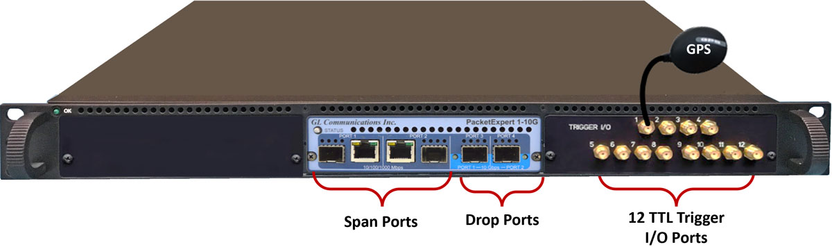
The Packet Analyzer and Discrete Signal Logger products are all 1U rack platforms based on the same GL’s PacketExpert™ Ethernet/IP hardware; their functionalities differ through scripts that cater to different needs of test cycle. GL offers PacketExpert™ 10GX (PXN100) Ethernet/IP hardware platform support four 1G ports on the unit. This tool is equipped with optional TTL I/O ports to trigger events of interest occurrence during tests.
Packet Analyzer
Measuring delay, jitter and packet loss through these networks is critical and network testers will need to precisely time events. Understanding the time from which the Air Traffic Controller keys PTT until the IP stream indicates that the PTT bit is set is a relevant testing scenario. This delay measurement is possible using GL's Packet Analyzer - PacketExpert™. The Packet Analyzer is capable of generating event driven triggers based on certain packet filters. For each packet that satisfies filter criteria that will be forwarded for timestamping and synchronizing with other equipment.
Packet Analyzer hardware is capable of modifying the filtered packets using an inband method to convey information such as Timestamp (8 Bytes), Board Serial No. (1 Byte), Port No. (4 Bits), and Filter No. (2 bytes), to the output ports in the packet's MAC header.
| PacketExpert™ 10GX (PXN100) |
|---|
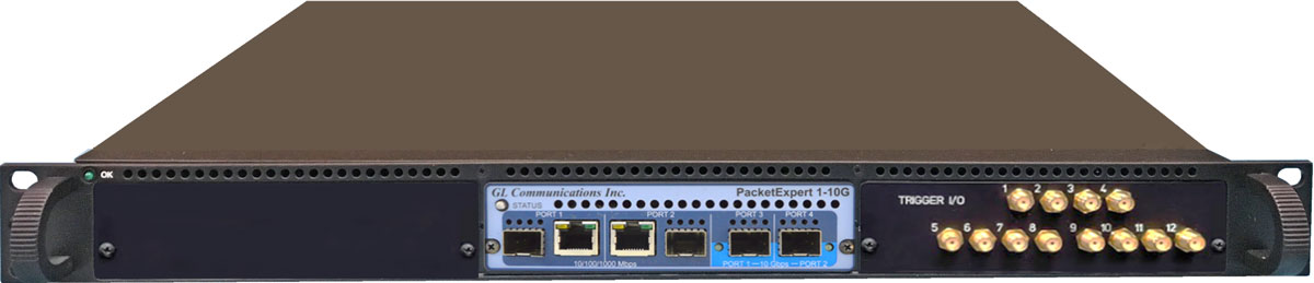 PacketExpert™ 10GX (PXN100) 1U Rack Unit |
|
Interface:
|
Dimension:
|
|
Power Supply: 100-240 VAC |
Connectivity:
|
Audio Analyzer (1U Rack)
GL's Audio Analyzer is a 1U rack platform that uses VQuad™ Dual UTA HD as the base hardware combined with SBC for PC interfaces. The Dual UTA HD hardware includes two PTT/Audio channels/ports and 8 TTL triggers.
Audio Analyzer can be used to simulate PTT or Squelch on the radio interface using the PTT/Audio interface on the device With VQuad™, it is capable of automatically keying PTT from the CWP, then transmit and receive audio signals, and generate TTL triggers based on send and detect audio actions.
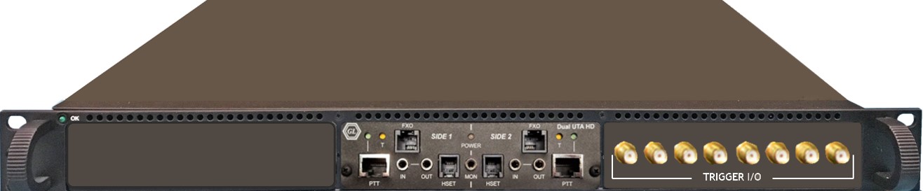
Audio Analyzer – 1U Rack Unit
Audio Analyzer – Dual UTA |
Dual UTA HD w/ Embedded Single Board Computer (SBC). SBC Specs: Intel Core i3 or optional i7 Equivalent, Windows® 10 64-bit Pro Operating System, ATX Power Supply, 240GB Hard drive, 8G Memory (Min), Two HDMI ports (Optional VGA to HDMI interface) |
Interfaces |
|
Features |
|
Dimension |
Length: 16 Inches |
Power Source |
ATX Power Supply |
Connectivity |
1 x USB 2.0 (or 10/100 Mbps Management Ethernet) |
Working Principle
MAPS™ TM-ATM (Timing Measurements in Air Traffic Management) components can be broadly categorized into two sets based on the underlying hardware:
- Packet Analyzer, Discrete Signal Logger– All these are based on the same GL’s PacketExpert™ Ethernet/IP hardware; their functionalities differ through scripts that cater to different needs of test cycle and software based Event Data Logger
- Audio Analyzer – This is based on VQuad™ Dual UTA HD hardware which includes 2 audio interfaces and 8 TTL triggers; Audio Analyzer can be used to simulate PTT or Squelch on the radio interface using the PTT/Audio interface on the device
All components of MAPS™ TM-ATM are controlled by a centralized component called MAPS™ Administrator (TM-ATM Client). MAPS™ TM-ATM support a client server model, with components acting as servers, the MAPS Admin acts as a client and controls all components acting as servers, from a centralized location.
Some examples of critical timing measurements that can be performed within the Air Traffic Management systems are:
- Audio Transmitted from near-side CWP – to – Audio Received at far-side radio interface
- PTT Disabled at near-side CWP – to – Audio Stopped at far-side radio interface
- Audio Transmitted from near-side CWP – to – Audio Received at Ground Radio Station output
- PTT Enabled at CWP – to – PTT bit set to On within RTP packet exiting CWP
- PTT Disabled at CWP – to – PTT bit set to Off within RTP packet exiting CWP
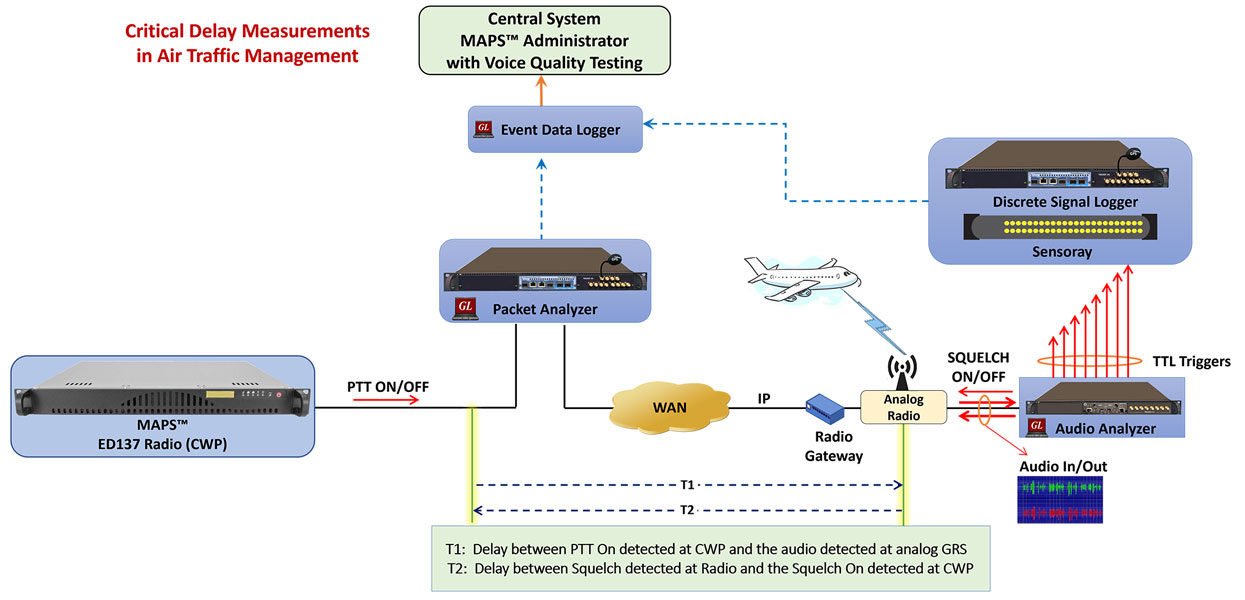
The time from which an Air Traffic Controller depresses the PTT until the IP stream indicates that the PTT bit is set is an important testing example. This delay measurement is possible using GL’s Audio Analyzer and GL’s Packet Analyzer. Both are capable of generating TTL triggers based on PTT activation. The Packet Analyzer is capable of generating Packet and TTL triggers based on real time packet detection, filtering, and capture as necessary.
A remotely located MAPS™ Administrator instructs GL’s Audio Analyzer connected to a CWP to send audio and simultaneously generate a TTL trigger. The Discrete Signal Logger connected to the Audio Analyzer can detect the TTL trigger and post an event to the Event Data Logger. On the IP side, GL’s Packet Analyzer which is monitoring the line non-intrusively can detect the packets of interest (e.g. first RTP packet with PTT bit set) based on the filters set and post an event to Event Data Logger. Centrally located the Event Data Logger time tags these received events and reports these events to the MAPS™ Administrator. The MAPS™ Administrator will calculate the time difference between different events posted and reports the measured delay.
Test Tools for Delay Measurement
The following outlines the GL Tools used and their functionalities for Timing Measurement:
Audio Analyzer - The Audio Analyzer is a two 4-wire audio device that can connect to a CWP and emulate a controller by transmitting audio. It supports PTT interfaces to connect to CWP Dual Jack Module and other 4-wire interfaces. It can send a PTT signal through 4-Wire interface exactly as though a real user is holding PTT on the headset. It can also inject and record analog signals at CWP, Radio and VoIP gateway interfaces. The analyzer can generate TTL for different actions (PTT ON, PTT OFF, Send Audio, Detect Audio). The Audio Analyzer can also be utilized in other areas of the network where analog audio signals are present.
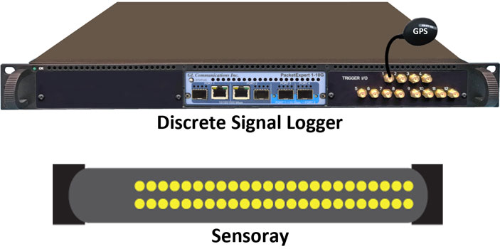
Discrete Signal Logger - The Discrete Signal Logger works with the Audio Analyzer and Sensoray to convert analog events into packet events. It continuously monitors the TTL inputs to Sensoray and the TTL output from the Audio Analyzer at regular intervals. The Sensoray can also generate analog control signals (PTT/Squelch etc.) that can be controlled from the Discrete Signal Logger. Each time it receives a trigger pulse, it promptly generates a TELNET packet containing all the necessary information, including the corresponding channel number. The filtering module efficiently filters and timestamps these relevant TELNET packets before routing the Discrete Events to the Event Data Logger. The Discrete Signal Logger generates the packets, which are named Discrete Events, indicating the occurrence of events at the analog interface.
Packet Analyzer - It functions like a highly precise Ethernet tap. It acts as a transparent Ethernet link in which bidirectional Ethernet traffic flows through at line rate. Additionally, Packet Analyzer can filter certain packets of interest from both directions without disturbing the traffic. The filtered packet's first 12 bytes of the MAC header is modified (overwritten) with useful information such as the filter number, port number, and device ID. These modified packets generated by the Packet Analyzer are named as Timed Events and are forwarded to the Event Data Logger.
The Packet Analyzer can aggregate filtered and modified packets from both directions and forward over a single output port.
Packet Analyzer also supports generating output TTL signal pulses for every filter match, so that the TTL signal (representing the Filter match) can be taken out and processed using an external device like Oscilloscope.
Event Data Logger - The software based Event Data Logger receives the packets forwarded from Discrete Signal Logger (Discrete Events) and Packet Analyzers (Timed Events). Each received frame, will be decoded for the timestamp and clock source information. For these frames notification will be generated to MAPS™ Administrator (MA) with timestamp and Clock Source information. Event Data Logger also processes each of the frames received to detect the start of voice burst and report it to the MAPS-Administrator.
MAPS™ Administrator (TM-ATM Client) - The MAPS™ Administrator is a control/logging application, and it uses TCP/IP to send commands to and receive notifications from all the above-mentioned tools (PacketAnalyzer, AudioAnalyzer, Discrete Signal Logger, EventDataLogger). MAPS™ Administrator will calculate the time difference between posted events, i.e., Discrete Events and Timed Events (from Packet Analyzer) and reports precise measured delay at different points in the network. MAPS™ TM-ATM is script based and API driven products that can be reused for various purposes during test cycles.
Measurement of TTL Triggers
When Audio Analyzer performs a certain function, it simultaneously sends a discrete TTL pulse to the Discrete Signal Logger. Audio Analyzer include two audio channels and 8 TTL ports, each audio channel controlling the 4 TTL ports. When the Discrete Signal Logger receives this pulse, it creates and transmits a timestamped packet indicating which pulse it received. This allows us to get analog and digital events into the same log for delay measurement. Further this packet is filtered out by the Packet Analyzer and forwarded. Up to 16 filters can be operated simultaneously per port. For every packet that successfully passes a filter, the Packet Analyzer can generate TTL Triggers to indicate this event.
The analog signals timing relationship of both Audio Analyzer and Packet Analyzer can be verified by connecting the TTL I/O Ports to Oscilloscope using SMA cables.
The following is explained for signal monitoring at one audio channel and output on 4 TTL ports, the functionality is same for the other audio channel available and other 4 TTL ports.
Following signals can be monitored at Audio Analyzer TTL Output ports –
- When a PTT signal is sent through 4-Wire interface of Audio Analyzer, exactly as though a real user is holding PTT on his/her headset, a TTL Pulse is sent out on TTL Port 1 to Discrete Signal Logger for packetization
- When PTT signal on 4-Wire interface stops TTL is Pulse sent out on TTL Port 2 to Discrete Signal Logger for packetization
- TTL Pulse is sent out on TTL Port 3 at start of transmission of Pre-recorded voice file
- TTL Pulse is generated out TTL Port 4 when audio is detected (i. e. not when the command is executed, like the other triggers)
Following signals can be monitored at Packet Analyzer TTL Output ports –
Packet Analyzer can define 2 filters per port, each of which is mapped to the TTL I/Os as shown in the table below:
| Ports | Filters | I/O |
|---|---|---|
| Port1 | Filter1 | I/O 1 |
| Filter2 | I/O 2 | |
| Port2 | Filter1 | I/O 3 |
| Filter2 | I/O 4 |
- When Port 1 filters (Filter1 and Filter2) each have one matched packet, corresponding mapped TTL Port1 and Port2 generate a single TTL pulse, which can be viewed on a connected oscilloscope
- When Port 2 filters (Filter1 and Filter2) each have one matched packet, corresponding mapped TTL Port3 and Por4 generate a single TTL pulse, which can be viewed on a connected oscilloscope
- The number of trigger pulses generated on TTL Ports exactly matches the filter match count
Simulation Test Tools in ATM
MAPS™ ED-137 Radio and Telephone Emulators - GL's MAPS™ ED-137 Radio and MAPS™ ED-137 Telephone emulators can simulate Radio and Telephone calls as per EUROCAE's ED137-1B and ED137-2B specifications. Using Bulk Call capability of these tools user can generate hundreds of calls as background traffic while making delay measurements. Good sample applications can be to simulate real time scenarios like PBH and PBM by generating required bulk calls in the background.
IPNetSim™ – GL's IPNetSim™ an IP Network Emulator connects to the 2 end points of a WAN link, allowing it to be configured to act either as a transparent bidirectional Ethernet link or a simple Ethernet bridge between 2 end points. It emulates a 10 Gbps or a 10/100/1000 Mbps full duplex link. . The incoming traffic can be identified into separate user defined stream for each direction, which can then be modified to simulate network malfunctions. Each direction supports up to 16 streams, allowing up to a total of 32 streams in both directions.
IPNetSim™ supports various impairments like:
- Bandwidth emulation from 100 Kbps up to 10 Gbps in increments of 1 Kbps emulating various WAN technologies like Modem, DSL, T1/E1/T3/E3/OC-3/OC-12 etc
- Latency/Delay emulation from 0 milliseconds to 8 seconds, with single, uniform and random distributed delay emulation capabilities
- Packet Loss emulation, from 0 to 100%
- Packet Reordering emulation, from 0 to 100% with random reinsertion delay
- Packet Duplication emulation, as a percentage of total packets, from 0 to 100%
- Logic Error Insertion - inserts error anywhere within the frame, from 10-1 to 10-9 rate
Resources
| Item No. | Item Description |
PKS118 |
|
PKS119 |
|
| PKS117 | MAPS™ ED-137 Recorder |
PKS107 |
RTP EUROCAE ED-137 |
| PKS170 | CLI Support for MAPS™ |
| PKS102 | RTP Soft Core for RTP Traffic Generation |
| VQT245 | Dual UTA - 4 Port TTL Option |
| PXN100 | |
| ATM Solutions | |
|---|---|
ATM501 |
MAPS™ Administrator (no VQT) |
ATM501a |
MAPS™ Administrator with VQT (POLQA) |
ATM501b |
MAPS™ Administrator with VQT (PESQ) |
ATM501c |
MAPS™ Administrator with VQT (POLQA and PESQ) |
ATM501d |
MAPS™ Administrator with Multi-Threading and VQT (PESQ) |
ATM501e |
MAPS™ Administrator with Multi-Threading (no VQT) |
ATM501f |
MAPS™ Administrator with Multi-Threading (no VQT) with additional Load Support |
ATM502 |
MAPS™ ED137 Radio Emulator (w/Host Server) |
ATM502b |
MAPS™ ED137 Telephone Emulator (w/Host Server) |
ATM502c |
MAPS™ ED137 Recorder Emulator (w/Host server) |
ATM502d |
MAPS™ ED137 Telephone Emulator (w/Host Server) and Addendums 4 and 5 |
ATM503 |
1-Port Audio Analyzer with 4 TTL |
ATM503a |
2-Port Audio Analyzer w 8 TTL |
ATM503b |
4-Port Audio Analyzer with 16 TTL |
ATM503c |
2-port Audio Analyzer with E&M and 8 TTL |
ATM503p |
2-Port Portable Audio Analyzer with 8 TTL |
ATM504R |
Packet Analyzer, rack version |
ATM504P |
Packet Analyzer, probe version |
ATM506 |
Discrete Signal Logger with 96 Ports (PXN) |
ATM507 |
IPNetSim™ |
ATM508 |
PacketScan™ NetsurveyorWeb™ Lite (w/Host Server) |
ATM508a |
PacketScan™ Analysis (w/Host Server) |
ATM509 |
Software Event Data Logger |
ATM510 |
Audio Analyzer with tProbe™ and 8 TTL, Includes 2-wire FXO/FXS and 4-wire SS1/SS4 |
ATM510a |
Audio Analyzer with tProbe™, Dual UTA, 4W FXO/FXS Adaptor and 12 TTLs. Supports 4W FXO/FXS interfaces |
ATM008 |
24-Port Programmable Switch |
ATM008a |
48-Port Programmable Switch |
ATM008b |
Cisco 9300-48T-A Switch |
SA053 |
Analog Converter with embedded Sensory |
| Related Software | |
| PKV100 | PacketScan™ (Online and Offline) |
| PKV120 | PacketScan™ HD w/4 x 1GigE |
| PKV120p | PacketScan™ HD w/4 x 1GigE - Portable |
| Related Hardware | |
IPN507 |
IPNetSim™ & IPLinkSim™ Options for 1G, 2.5G and 10G |
| Presentations |
| Test Solutions for ATC Presentation |
| Signaling and Traffic Simulation using MAPS - Presentation |