Dual UTA HD : HD Audio and Versatile Testing Capabilities
Ideal for Mobile Phones, Bluetooth® Devices, Mobile Radios, POTS Lines, and Analog Interfaces
Latest Software
- VQuad™ Software Ver 11.4.9
- Voice Analysis Tool (VAT™) Ver 1.2
- VQT Software Ver 8.2
- WebViewer™ (ORACLE & MySQL) Ver 7.0
- AutoVQT™ Software Ver 2.3
Request a Demo / Quote
Brochures
Overview
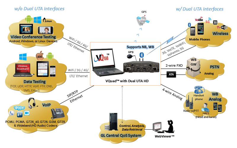
GL offers next generation Dual UTA HD hardware unit, which supports all the interfaces and telephony devices as that of Dual UTA unit in a smaller (compact) design, with most of the interfaces on front of the board. The Dual UTA HD is more compact than the previous Dual UTA and includes HD (WB) audio on all interfaces. The latest VQuad™ release also supports both the legacy Dual UTA (v.1) along with the next generation Dual UTA HD (v.2) connected to the same system simultaneously. Up to 12 fully independent devices can run simultaneously on each VQuad™ node, with multiple VQuad™ nodes running in unison for virtually unlimited capacity.
Additionally, the Dual UTA HD (v.2) includes support for testing HD voice using Bluetooth® Wideband, and FXO Wideband along with hardware loopback controlled through the VQuad™ software (including self-test mechanisms). Dual UTA HD hardware also includes Self-Test LED, GPS connect LED, enhanced flexibility added to the VQuad™ Script, and full IPV6 support.
The Dual UTA HD has two independent sides, Side 1 and Side 2. Each side is used to interface with a different network or endpoint. For example, Side 1 could be used to connect to a Bluetooth with 5G mobile, while Side 2 could be used to connect to a analog phone.
As many as 6 Dual UTA HD units can be connected to single GL's VQuad™ software application, simplifying the end-to-end testing of voice, data, video quality, Echo & Delay measurements, and FAX in variety of networks, including Wireless (Bluetooth®, Wi-fi, 3G, 4G, LTE, PTT Mobile Radio), VoIP, Analog, and TDM, practically allowing any end-point interfaces.
Enhanced VQuad™ with Dual UTA HD supports two methods of automated testing of mobile devices, Bluetooth and Wired Headset using GL’s new cable, Smartphone with Automated Call Control (ACC). Through the VQuad™ script (or manual operation), calls can be setup and send messages using iPhone SIRI or Android Google Voice available on mobile devices. VQuad™ includes Text-to-Speech technology for automatically creating the necessary voice prompts required to work with Siri or Google Voice.
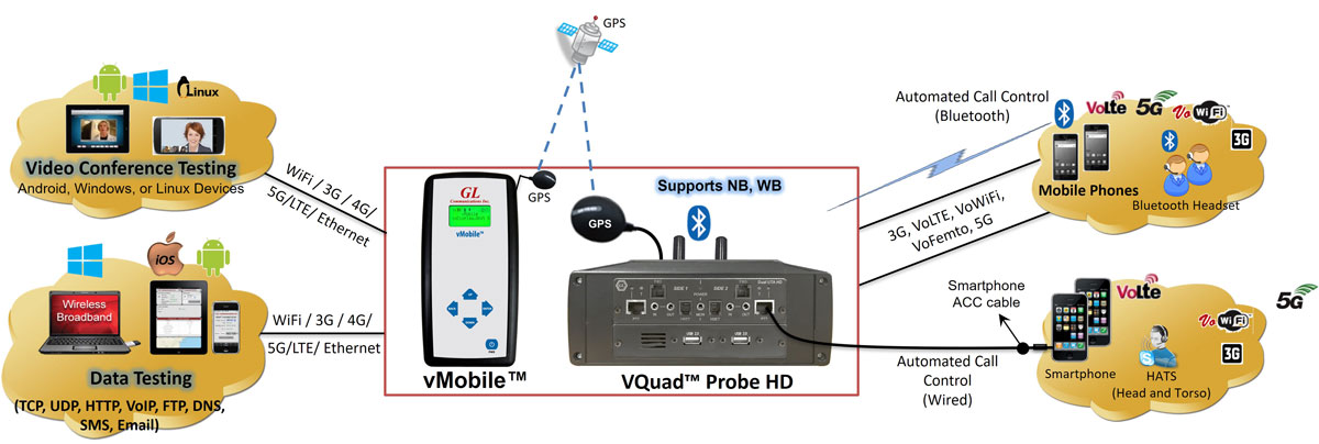
vMobile™ - Ultra-Portable Equipment for Voice & Data Testing
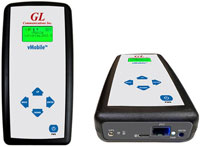
The vMobile™ - Portable VQT Test Solution is a handheld device which can support full audio testing for mobile phones and mobile radios, as well as providing data testing for mobile phones. The vMobile™ can be hand-carried for walk and drive testing (includes GPS) as well as left in labs and can work directly with GL’s VQuad™ solution for very flexible end-to-end testing. All functionality and configuration of the vMobile™ is accessed using the remote web-based Console or Console App which is installed on any Android or iOS device.

Supported Hardware Interfaces
- Mobile Phones:
- Bluetooth® – Works with all Bluetooth® phones for both call control and send/record audio functions. Bluetooth® also performs RSSI, Battery level functions, Network verification. Supports Bluetooth Narrow Band (NB) with Frequency Range 204Hz to 3404Hz, Wideband (WB) with Frequency Range: 204Hz to 7200Hz.
- Mobile audio interface for Smartphones (iPhone, Android) – includes Audio Headset Jack - 2.5mm (typical) for mobile phones, 3.5mm terminations for Smartphones (iPhone, Android)
- Wired Headset Smartphone ACC connectivity - connects the mobile phone to the Dual UTA HD PTT interface using the GL Smartphone Automated Call Control (ACC) cable
- Mobile Radios with Push-to-Talk functionality: Provides radio keying and sends/records audio.
- RJ-11 POTS lines: Detect dial tone, go off hook, CallerID detection, send digits (two stage dialing), answer calls, detect a variety of Special
Information Tones (SIT), and much more as well as send/record audio for Voice Quality measurement. - Handset Phones (POTS, Digital, VoIP): Replaces handset of any telephone (POTS, Digital, VoIP) that contains a coiled cord and handset
- 2-wire Analog (WB, NB - FXO) supporting next generation gateways
- 4-wire analog interfaces supporting Tx/Rx Headset including HATS, Mobile Phone Headset, and any Handset Phone (RJ22 connection).
Hardware Specifications
Dual UTA HD Hardware Unit
Mechanical Specifications
Physical Dimensions |
Height: 1.60 in. (40.64 mm) |
External Connections |
|
USB Connection |
|
LEDS |
|
Terminal Block |
|
Electrical Specifications
Power Requirements |
|
||||||||||||||||||||||||
4-Wire (Balanced, HSET, PTT) |
Input:
Output:
|
||||||||||||||||||||||||
2 Wire Analog (FXO) |
Input:
Output:
|
||||||||||||||||||||||||
4-Wire Analog (Mobile) |
Input:
Output:
|
||||||||||||||||||||||||
Bluetooth |
|
||||||||||||||||||||||||
Power Measurement |
|
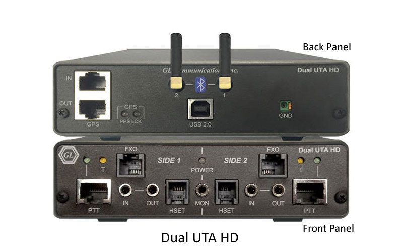
Dual UTA HD Connections
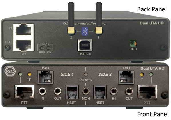
Front Panel
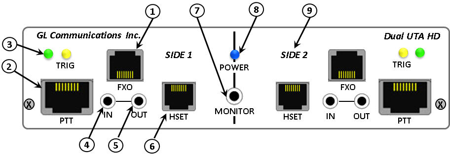
- FXO Jack: This RJ-11 jack gives the Dual UTA HD the ability to act as a telephone. This is a 2-Wire POTS interface that allows users to place calls, answer calls and utilize all of the Dual UTA’s voice quality and delay features.
- Push-to-Talk (PTT) with LEDs - Side 1 & 2: For use with radios that requires activation of a push-to-talk function to transmit or receive audio signals. There are two RJ-45 Jacks (PTT) one for each side of Dual UTA HD. The RJ-45 jack is connected to the software-controlled relay internal to the Dual UTA HD. When PTT is active (PTT LED on), pins 4 & 7 are shorted. A single RJ-45 PTT port includes the TX/RX 4 wires along with 2 wires for PTT operation (keying radio on/off).
PTT LEDs: When illuminated indicates that the PTT function is active. The active state indicates that the radio has been placed in transmit mode. Conversely, the inactive state (LED off) indicates the radio is in receiving mode.
- Trigger (TRG) LED: When illuminated indicates that a Round-Trip Delay (RTD) or One-Way Delay (OWD) pulse has been detected. This LED may also illuminate momentarily when connecting or disconnecting audio lines.
- In Jack: This 3.5 mm jack provides a balanced Audio In port. This jack can connect to a wide variety of the network interfacing equipment. Multiple impedance options are also available with this input.
- Out Jack: This 3.5 mm jack provides a balanced Audio Out port. This jack can connect to a wide variety of the network interfacing equipment. Multiple impedance options are also available with this output.
- Handset (HSET) Jack: This RJ-22 jack is used with handset-type phones. Connect the curly cord of the handset to this jack.
- Monitor Jack: This 3.5 mm output jack (stereo miniature phone type) provides for connection of a headset or amplified speakers to monitor the Audio In/Out signals on all interfaces.
- Power LED: When illuminated indicates the Dual UTA HD is receiving power and is ready to operate. The Dual UTA HD is powered from the USB bus.
- Side: The Dual UTA HD contains a Side 1 and Side 2. These sides are completely independent of each other, so Mobile Phone Network Testing could be setup on Side 1 while FXO Network Testing could be happening on Side 2.
Back Panel
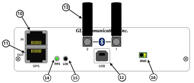
- GPS (In): RJ-45 Input jack from external GPS receiver. The Dual UTA HD uses location and time to provide additional information to the user. The one pulse-per-second GPS input will allow 1 ms accurate one-way and round-trip-delay measurement.
- GPS (Out): (RJ-45 Output jack) The Dual UTA HD allows the GPS received data on the GPS (In) port to be transmitted out the GPS (Out) port. This enables a single GPS receiver to provide data to multiple Dual UTAs.
- USB 2.0 Type B Jack: Communications and power interface connection. Connect to the computer USB port directly or through a USB hub.
- Bluetooth® (BT): The Dual UTA HD has Bluetooth® built in, which allows users to connect to Bluetooth® enabled devices. This provides call control (control of phones calling/answering functions) as well as the ability to send/record audio in/out of these devices.
- PPS: (GPS PPS Yellow/Green LED) When illuminated indicates that the GPS function is active. The active state indica
tes that the GPS has been placed in transmit mode. Conversely, the inactive state (LED off) indicates the GPS is in receiving mode.
- LCK: Programmable LED
- GND: Terminal block for ground connection
Network Types
Connectivity - Bluetooth® NB & WB, PTT, GPS, 4-wire Balanced I/O, Interfaces on Dual UTA HD
Devices – Military/Mobile Radios, 4G/3G/Wifi Smartphones (iPhone, Android, Blackberry), Bluetooth® Headsets/Stereo/Car Kits
Wireless networks can impair voice quality by various means including poor mobile phone quality, voice/video compression and decompression algorithms, delay, loss or gain in speech levels, noise, acoustic and landline echo, and other distortions.
GL provides a compact and portable solution for testing Wireless and Mobile Radio devices for voice, video, and data quality using the GL VQuad™ application with the Dual UTA HD, or all-in-one VQuad™ Probe. The Dual UTA HD includes interfaces for Push-to-Talk for mobile radios, and Bluetooth for connecting to any mobile phone.
Some of the important features include:
- Test mobile end-to-end voice, video, and data, quality measurement and analysis results
- Control Smartphones on any wireless network (Bluetooth®, 5G, VoLTE, VoWiFi, VoFemto, 3G) - - both NB and WB voice supported
- Mobile Phone call control – supports Bluetooth®, Dual PTT, 3.5mm Output Audio Jack, and Dual 3.5mm In/Out terminations
- Support for voice quality testing on VoLTE network with AMR Wideband codec (with 16000 Sampling Rate) using Bluetooth® Wideband
- Control Mobile Radios with Push-to-Talk functionality; Supports radio keying and send/record audio
- Bluetooth® option for Testing Bluetooth® Phones and Bluetooth® Headsets
- Bluetooth® also performs RSSI, Battery level functions, and Network identity
- Impair outgoing traffic using a noise file or user-defined white noise
- All results along with call control information are sent to central database. Query results remotely using the WebViewer™.
- Compatible with automated GPS location time-stamping
Some of these applications include
- Voice Quality Testing (VQT) software for analysis according to widely accepted ITU (International Telecommunications Union) voice comparison algorithms (POLQA, PESQ LQ/LQO/WB)
- Data Quality Testing (NetTest™)application for performing automated data testing on a wireless or wired network; tests include TCP, UDP, VoIP, Route, HTTP, FTP, DNS, SMS, Email, SIMInfo, Phone Info, and UEInfo
- Video Quality Testing (VAC™) application for performing fully automated Video Conference testing and get Audio and Video MOS QoS results along with several analytical metrics
- Echo Measurement Utility (EMU) for echo and delay measurements, including RTD, OWD, ERL, EPD, and more
- Voice-band Analyzer (VBA) for monitoring voice band traffic (Speech Level, Activity Factor, RMS Factor, DC Level, Noise Level, Jitter, Echo Return Loss, Echo Delay, and Echo Dispersion)
- Fax Quality Testing for emulation and analysis of T.30 faxes (GLInsight™ or FaxScan™)
- Drive Testing solution for plotting all results and call control information along with co-ordinates using GPS receiver option in VQuad™, and Google Maps option within WebViewer™
- WebViewer™ for web based controlling and monitoring VQuad™ nodes over the entire network
For more details, please visit Voice, Video, and Data Testing in Wireless Network webpage.
- Connectivity – 2-Wire FXO, 4-Wire Balanced I/O, HSET Interfaces on Dual UTA HD
- Devices – Analog Phones, Next Generation Gateways, PBX, ATAs over PSTN network
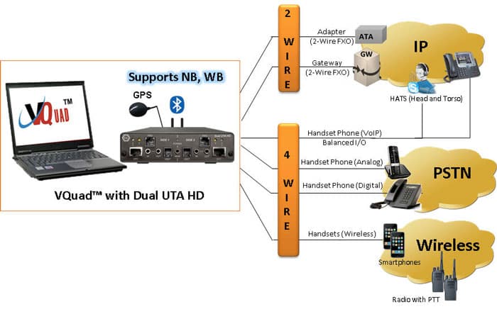
GL's VQuad™ with Dual UTA HD provides the solution for testing analog 2-wire interfaces (PSTN, ATA, Media Gateway). The Dual UTA HD supports 2 Analog FXO interfaces (RJ11) and provides Off/On- Hook, DTMF Dialing, Flash Hook, Tone Detection (Dialtone, Ringback, Busy, Fast Busy, SIT) and CallerID.
The Dual UTA HD Analog interface supports two-stage dialing, IVR testing, Voice Quality Testing, Delay Measurements, and Echo Measurements.
- Supports 2 independent FXO ports per Dual UTA HD
- Dual UTA HD connect to any PSTN, ATA, and next generation Gateways
- Global support – can connect to any 2-wire interface anywhere
- Wide Band (WB) and Narrow Band (NB) support (for HD and SD Audio)
- Manual or Automatic operation of traffic generation and full call control
- Each analog port may be controlled independently for traffic and call control
- Supports all standard and customized call progress tones
- Send/detect DTMF /MF digits, and tones of different frequencies (NB – up to 4 KHz, WB – up to 8KHz, SWB – up to 24 KHz)
- Support for No Call Control (Quick Connect) on FXO interface
- Call control with Caller ID detection and display
- Impair outgoing traffic using a noise file or user-defined white noise
- Full FXO Functionality via flexible Scripts
- All results along with call control information are sent to central database. Query results remotely using the WebViewer™.
- Additional functionalities –
- Voice Quality Testing (VQT) (POLQA, PESQ LQ/LQO/WB)
- Echo and Delay Measurements (RTD, OWD, ERL, EPD)
- Voice-band Analysis (Speech Level, Activity Factor, RMS Factor, DC Level, Noise Level, Jitter, Echo Return Loss, Echo Delay, and Echo Dispersion)
- Fax Testing (up to 4 simultaneous T.30 faxes)
For more details, please visit Automated Analog (2-wire, 4- wire) Voice Quality Testing webpage.
- Connectivity – Internal SIP cores within VQuad™ (SIP and H.323 Signaling - Does not require Dual UTA HD), 4-wire Balanced I/O, HSET Interfaces on Dual UTA HD
- Devices – VoIP Phones, Soft Phone, HATS

With the growing requirements for voice quality testing within VoIP networks, a major concern is testing the VoIP Network, VoIP phones, VoIP Softphones, and Analog Telephone Adaptors (ATA).
GL's VQuad™ with VoIP option, provides the ability to perform manual or automated tests on Softphones in the VoIP network.
The VQuad™ provides direct connection to the VoIP network with up to 12 user agents per VQuad™ connected simultaneously.
- Manual or Automatic call control (SIP protocol) with user-defined parameters for authentication and proxy
- SIP Call Control within VQuad™ supports handling up to 4 SIP cores, and support up to 12 User Agents.
- Time/Digit/Tone triggering of send/receive voice files.
- Testing Analog Telephone Adapters (ATAs)
- Supports outband DTMF/MF digits for RFC4733 and RFC2833.
- Impair outgoing traffic using a noise file or user-defined white noise
- Supports almost all standard Voice Codecs (G.722, AMR, G.729 & more).
For more information to voice-codecs webpage
- Additional functionalities –
- Voice Quality Testing (VQT) (POLQA, PESQ LQ/LQO/WB)
- Data Quality Testing (NetTest™) (TCP, UDP, VoIP, Route, HTTP, FTP, DNS, SMS, Email, SIMInfo, Phone Info, and UEInfo)
- Video Quality Testing (VAC™) (Audio and Video MOS)
- Echo and Delay Measurements (RTD, OWD, ERL, EPD)
- Voice-band Analysis (Speech Level, Activity Factor, RMS Factor, DC Level, Noise Level, Jiiter, Echo Return Loss, Echo Delay, and Echo Dispersion)
For more details, please visit VoIP Testing using VQuad™ webpage.
- Connectivity – T1/E1 Interface facilitated through GL’s T1/E1 Analyzer Hardware (ISDN and CAS Signaling - Does not require Dual UTA HD)
- Devices – Digital Phones, PBX, Media Gateways
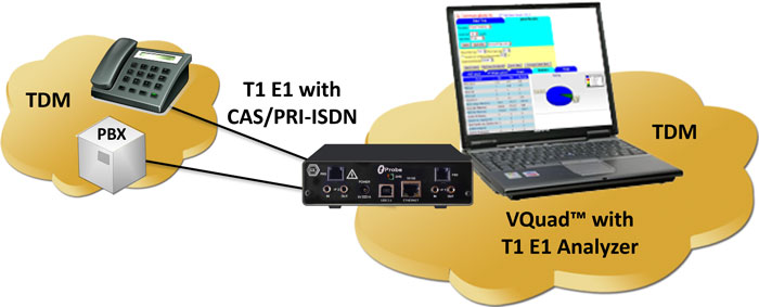
Using the T1/E1 Analyzer, the VQuad™ can generate and receive up to 12 simultaneous CAS or PRI ISDN or No Call Control (NOCC) calls on T1 or E1 trunks. Once the call is up, send/record voice via the VQuad™ to get VQT MOS results.
The T1/E1 option includes a script based CAS State Machine for creating any desired CAS protocol. Included with the PRI ISDN are all variants associated with ANSI and ETSI specifications.
- Supports Call Control for PRI ISDN and CAS Protocols
- Also supports No Call Control (NOCC), where the T1/E1 call is connected without any call control required.
- Send/detect DTMF /MF digits, and tones of different frequencies (NB – up to 4 KHz, WB – up to 8KHz, SWB – up to 24 KHz)
- Supports up to 12 simultaneous T1/E1 channels using VQuad™ interface
- Impair outgoing traffic using a noise file or user-defined white noise
- Additional functionalities –
- Voice Quality Testing (VQT) (POLQA, PESQ LQ/LQO/WB)
- Echo and Delay Measurements (RTD, OWD, ERL, EPD)
- Voice-band Analysis (Speech Level, Activity Factor, RMS Factor, DC Level, Noise Level, Jitter, Echo Return Loss, Echo Delay, and Echo Dispersion)
- Fax Testing (up to 4 simultaneous T.30 faxes)
For more details, please visit VQT in TDM Networks webpage.
Test Types
Delay Measurements
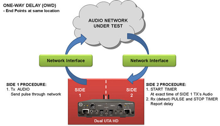
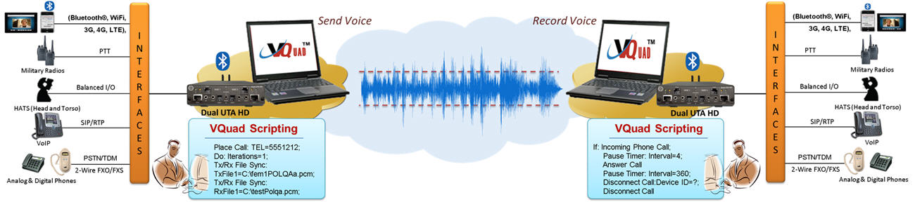
OWD - End points at same location
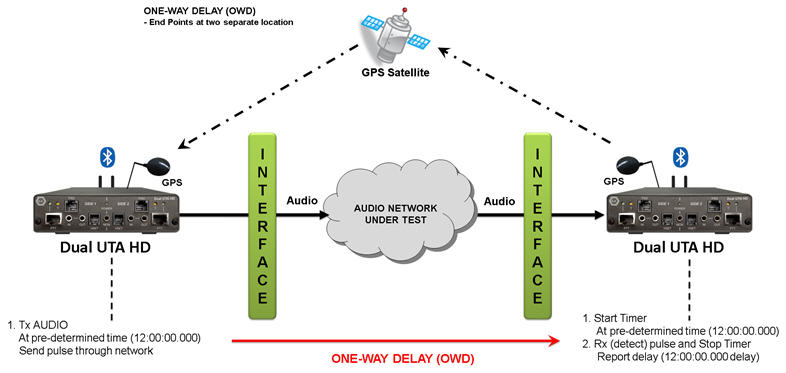
OWD - End points at separate location
- One Way Delay (OWD) - VQuad™ includes an advanced method for performing One Way Delay (OWD) measurements using a Correlator algorithm. The Correlator method is extremely accurate and works with the next generation Dual UTA HD
- Round Trip Delay (RTD) – the new method of measuring RTD using the Correlator algorithm supported on Dual UTA HD
- Post Dial Delay (PDD)
- Signal-to-Noise Ratio (SNR = S/N)
- Oscilloscope and Spectral Display
- RMS Power as well as C-Message
- Audio analysis of any recorded voice file for both Power and Frequency. RMS power and frequency response outputs are necessary for testing the network for full WB voice support.
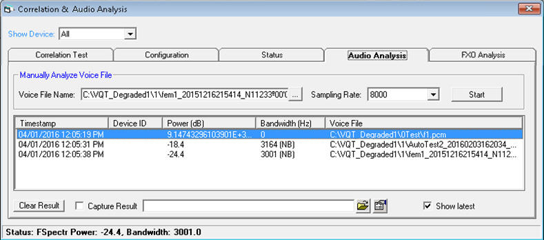
Audio Analysis
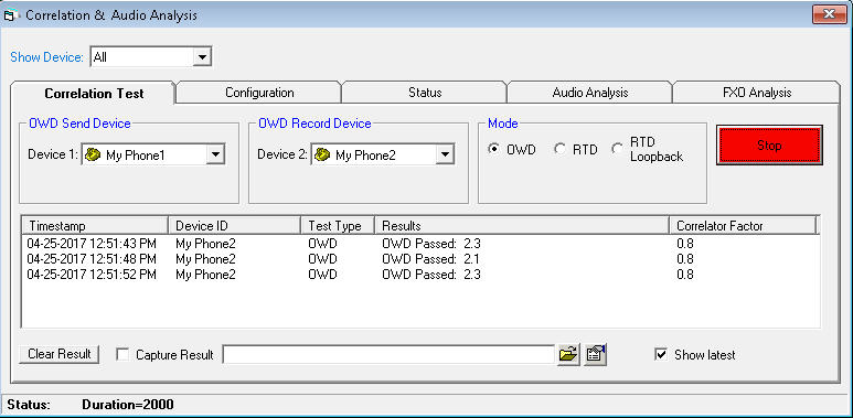
OWD using Correlator
For more details, please visit Network Delay Measurements webpage.
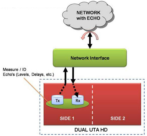
Echo Identification
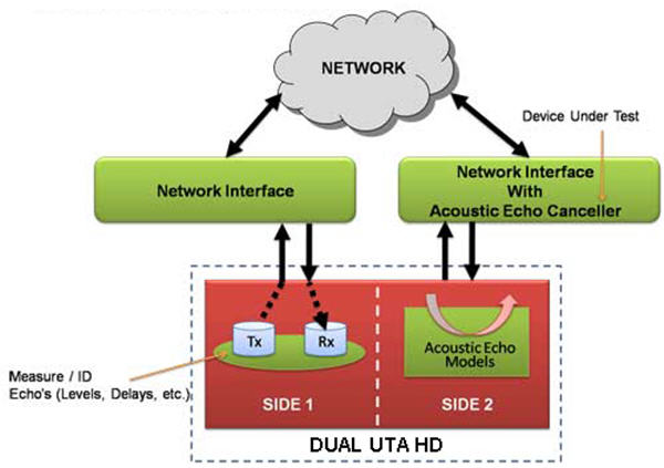
Acoustic Echo Canceller Testing
- Supports echo measurements over any network using EMU
- Assess sidetone, line, and acoustic echo and the corresponding delays.
For more details, please visit Echo Measurement Utility (EMU) webpage.
- Monitor voice band traffic
- Measure Active Speech Level, Activity Factor, RMS Factor, DC Level, Noise Level, Echo Return Loss, Echo Delay, and Echo Dispersion statistics.
For more details, please visit Near Real-time Voice-band Analyzer webpage.
Automated Voice Quality Measurement
- Network-independent VQT – Supports legacy, as well as Next Generation networks
- POLQA (ITU-T P.863)
- PESQ (ITU-T P.862), PESQ LQ, LQO (P.862.1), PESQ WB (P.862.2)
- Call control analysis (Failed Calls, Dropped Calls, and Call ID)
- Monitoring IVR System for voice and data quality
- Supports PESQ/POLQA (both NB and WB) measurements
- Supports both Narrow band (NB) and Wideband (WB) audio codecs (both 8k and 16k samples/sec)
- Auto detects voice files with wideband attributes
- All VoIP Codec supported including - G.711, G.711 App II with VAD, G.729, G.726, G.726 with VAD, GSM, AMR NB and WB, EVRC, SMV, iLBC, SPEEX NB and WB, G.722, and G722.1.
Visit Voice Codecs webpage for more comprehensive information.
For more details, please visit Voice Quality Testing (VQT) Software webpage.
VQuad™ is enhanced to support Data Testing including TCP, UDP, VoIP, Route, HTTP, FTP, DNS, SMS, Email, PhoneInfo, SimInfo, and UEInfo. The Data Tests are configured via the VQuad™ scripting and supports Wireless devices as well as PC Ethernet connections (wired, WiFi, Broadband 3G/4G, and LTE).
- Network independent, supports 4G LTE, 3G, WiMax, and Wired Internet connections
- Supports Mobile devices (i.e. iPhone, Android)
- Supports PC Ethernet connection (Wired, Wi-Fi, Broadband (3G or 4G))
- Different type of tests supported - TCP, UDP, HTTP, FTP, DNS, VoIP, Route, SMS, Email, PhoneInfo, SimInfo, and UEInfo.
- End-to-End SMS Testing over wireless network directly and remotely
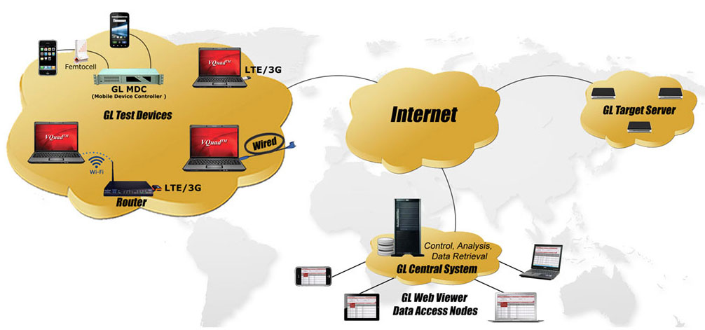
- Remotely perform Data tests from GLNetTestApp on mobile devices (iPhone, Android); this requires connection with Mobile Device Controller server. Mobile device communicates with Mobile Device Controller from anywhere in the world.
- Fully automated and remote testing with all results accessible via WebViewer™.
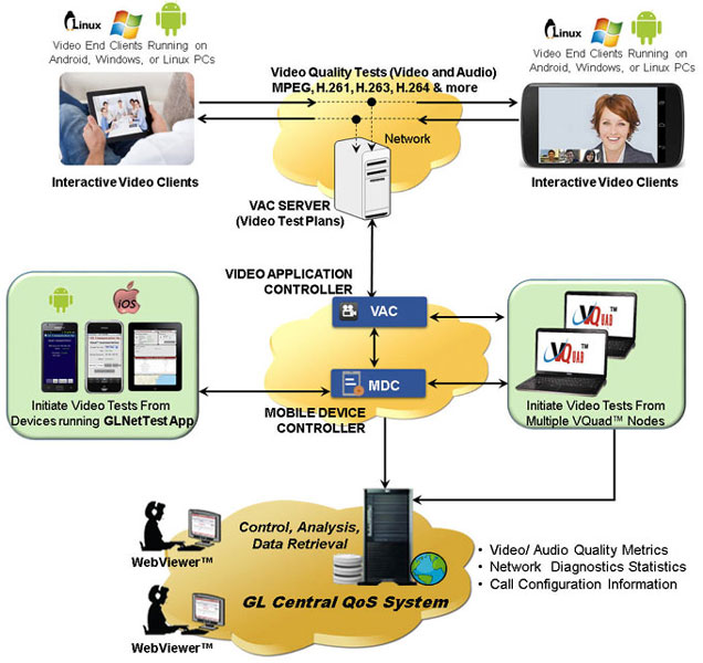
VQuad™ can now initiate, control, test, and measure video conferencing services over IP, and Wireless networks, using additional support of a Video Controller/Server and Video Clients (Agents).
Video Tests can be configured between any two active video clients with flexibility of specifying the typical characteristics of the Video test. Video Test agents generates simulated video calls to other test agents as per these test parameters.
- Fully automated Video Conference testing performed with QoS results provided along with several analytical metrics
- Support for Android, PC and Linux based video clients (end points) for active Video Quality Testing
- Both manual and automated tests are supported
- Tests can be run directly from the Android phone or using the VQuad™ interface
- Configure unlimited test plans; video test parameters include Codec, Bandwidth, Latency, Frame Rate, GoP (Group of Pictures) Structure, Echo, and Resolution
- Test results include Video MOS, Audio MOS, and A/V MOS along with a variety of analytical and quality metrics
- Fully automated and remote testing with all results accessible via WebViewer™.
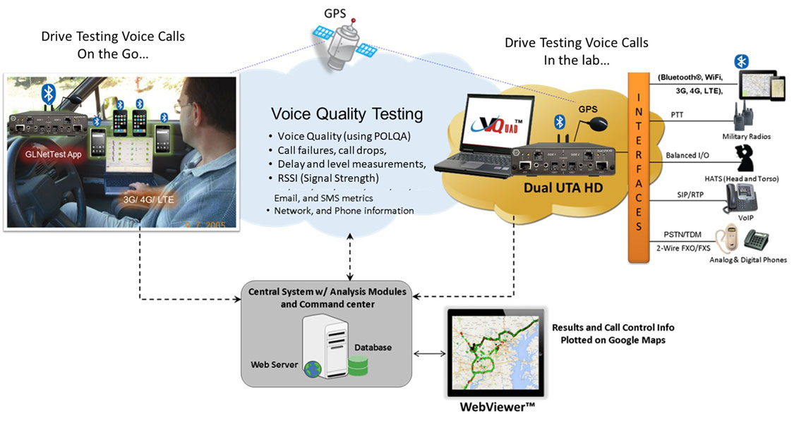
- Drive test with any Wireless device with real-time GPS mapping
- GPS connectivity for recording timing and location of tests performed
- The GPS mapping records and adds the real-time GPS information to all test results and VQuad™ call control.
- GPS Location includes stamping each result with Latitude, Longitude, and GPS Time Stamp
- The Indoor Tracking System (ITS) in VQuad™ is developed to support VQT in remote locations where GPS signal is unavailable
- The ITS information (location, timestamp) is saved to the database per VQuad™ Measurement
- GPS information is automatically sent to central database and accessed via Google Maps feature in WebViewer™.
For more details, please visit Drive Testing webpage.
- Supports Fax testing (sending and receiving) up to 4 independent and simultaneous T.30 faxes over 2-Wire, and 4-wire analog networks
- Support higher resolution and multi-page fax TIF files
- Tx and Rx fax rate from 2400 baud to 33600 baud with V.34 fully supported.
- Interfaces supported for fax generation include 2-wire FXO and 4-wire analog.
- Automatically save the fax session (both East and West directions) to a PCM file.
- Supports higher resolution and multi-page fax TIF files.
- Use GLInsight™ or GL Fax Scan analysis software packages for further analysis of the recorded fax files. GL's FaxScan™ can be configured for fully automated analysis.
- Simulate IVR Users and IVR System
- Single-box portable solution and Rackmount PC solution for higher density
- Complete automation with enhanced scripting and remote operation including traffic generation and call control scripting
- Automate the IVR testing process - call establishment and traffic generation detection process through scripts
- Monitoring IVR System for voice and data quality
- Perform Quality of Service (PESQ) or path confirmation tests
- Within a proper voice call, additional analysis is available such as Round Trip Delay (RTD) and Voice Quality Testing (VQT)
- Support for Command Line Interface (CLI) to access VQuad™ remotely
WB Bluetooth Testing
The VQuad™ with Dual UTA HD units can connect to any network or any end-equipment supporting HD (WB) audio on all interfaces. The Dual UTA HD includes interfaces for 2-wire analog FXO, 4-wire analog (Tx/Rx), Push-to-Talk for mobile radios, and Bluetooth for connecting to any mobile phone.
With the Dual UTA HD Bluetooth® option, the Dual UTA HD act as a Bluetooth® Headset and connects to the mobile phone to perform voice quality analysis along with delay measurements on Bluetooth® enabled mobile devices.
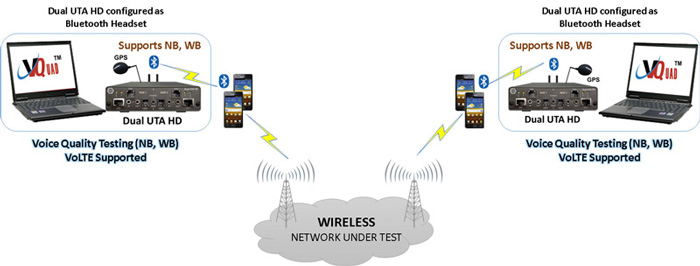
Test Bluetooth® Enabled Mobile Devices and Associated Network
As a new feature of the Dual UTA HD Bluetooth® option, and using special firmware, the Dual UTA HD can act as the Mobile Device and connect to any Bluetooth® headset to perform ‘Voice Quality Tests’ on the Bluetooth® Headsets. In other words, isolate the Bluetooth® headset for voice quality analysis.
This is extremely important for testing Bluetooth® headsets, Bluetooth® in the car, and pretty much any Bluetooth® device which connects to a mobile phone for voice. The Dual UTA HD connects to the Bluetooth® headset and allows voice quality analysis along with delay measurements. Both narrowband and wideband codecs are supported.
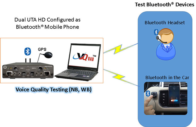
Test Bluetooth® Devices (Headsets, Car Stereo Kit …)
- Mobile (3G, VoLTE, VoWiFi, VoFemto, 5G) network with both NB and WB voice
- Mobile Phone call control – supports Bluetooth® 2.5mm Audio Headset Jack interfaces, and 3.5mm terminations for Smartphones (iPhone, Android)
- Support for voice quality testing on VoLTE network with AMR Wideband codec (with 16000 Sampling Rate) using Bluetooth® Wideband
- Control Mobile Radios with Push-to-Talk functionality; Supports radio keying and send/record audio
- Bluetooth® also performs RSSI, Battery level functions, and Network identity
VQuad™ with Dual UTA HD – WB 2-wire Analog FXO
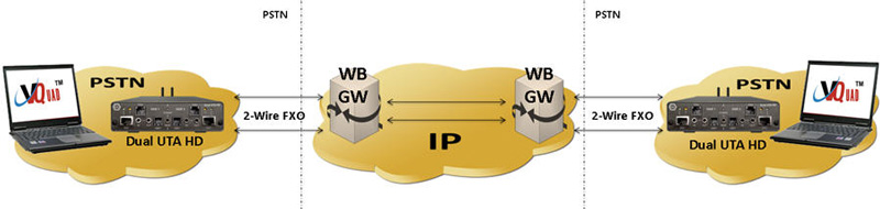
- Connect to any PSTN, ATA, and next generation Gateways
- Global support – can connect to any 2-wire interface anywhere
- Supports 2 independent FXO ports per Dual UTA HD
- Wide Band (WB) and Narrow Band (NB) support (for HD and SD Audio)
- Full FXO Functionality via flexible Scripts
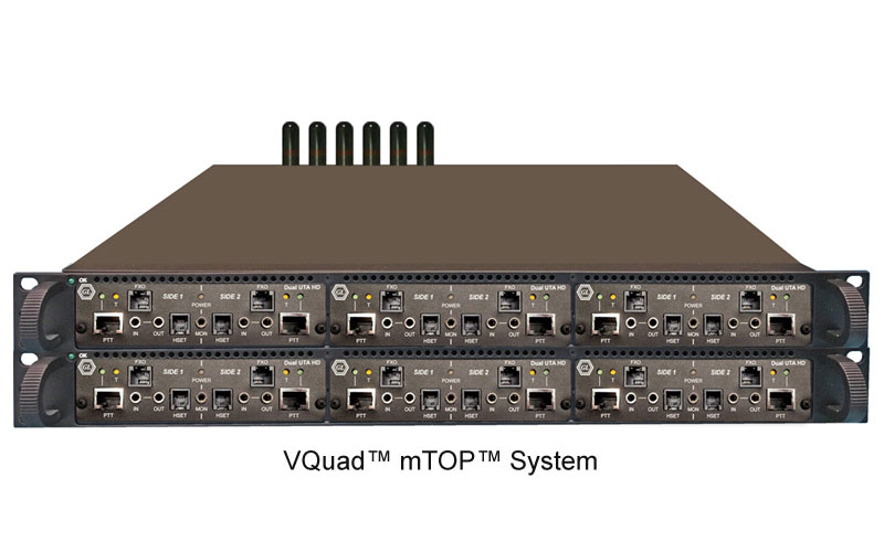
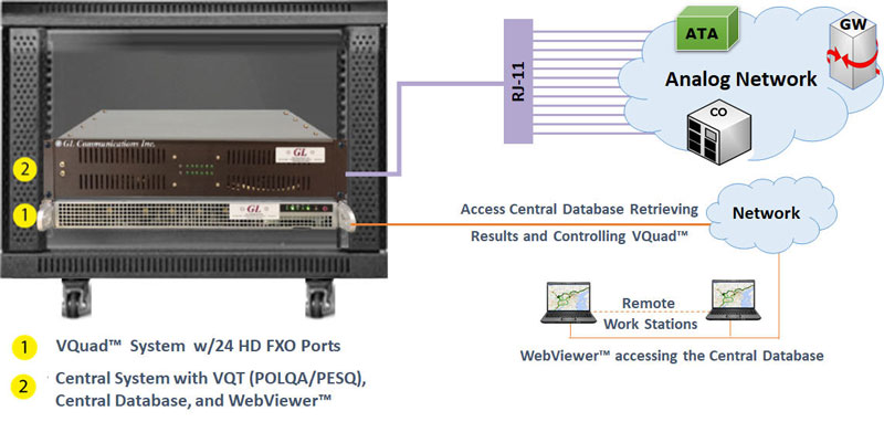
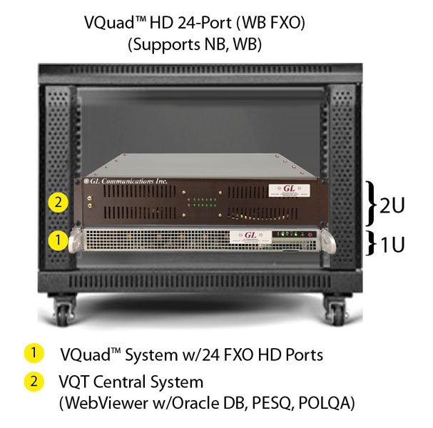
24-Port VQuad™ HD Analog Phone Simulator
VQuad™ 24-port HD FXO solution is an all-in-one 2U rack supporting both Wide Band (WB) and Narrow Band (NB) Audio. The 2U VQuad™ HD FXO system incorporates two embedded SBCs (Single Board Computer), each running latest VQuad™ software, along with 12 Dual UTA HD units supporting a total 24 FXO Analog ports. All 24 FXO ports are independent and can be fully automated or remote controlled for a fully autonomous test solution. Access to the 24 Analog ports is via an Amphenol connector on the back of the system which can be broken out to 24 RJ11 connections. Each embedded SBC includes two Gigabit Ethernet connections, two USB connections, and a VGA monitor connection. LED lights on the front of the 2U Rack display status of each SBC along with each Dual UTA HD.
Multiple VQuad 24-Port FXO Racks can be connected together for virtually unlimited FXO ports. When combined with the WebViewer Central System all results and events can be saved directly to a Central Database and accessed using the WebViewer (direct access to the database tables is also available). Analysis is provided using GL Voice Quality Analysis (both POLQA and PESQ supported), Echo Measurement Utility (EMU), Fax Analysis, and Voice Band Analyzer (VBA).
- Supports 24 independent HD FXO ports per VQuad™ system (2U)
- Scalable solution for unlimited number of FXO ports
- Wide Band (WB) and Narrow Band (NB) support (for HD and SD Audio)
- Multiple Users and Tests per system
- Run tests between systems
- Fully automated and remote accessible via CLI
- Remote accessible via Central Database
- Full FXO Functionality and Analysis via flexible Scripts
 VQuad™ 24 Port HD connected to Third-party DUT |
VQuad™ 24 Port HD Unit |
Supported FXO Functions and Analysis
Basic telephony functions |
FXO Call Progress and Services |
FSK related functions |
Traffic |
VQuad™ with Dual UTA HD – WB 4-wire Analog
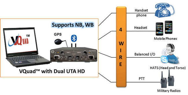
- Balanced – replaces headset (mic/speaker) anywhere
- RJ22 – replaces the phone Handset on any phone at the Curly Cord
- PTT (Push to Talk) – connect to any mobile radio (DoD, Emergency Services, Government) and supports voice and keying the radio
- Mobile – connect to any mobile phone, the phone will recognize the Dual UTA as a headset.
VQuad™– WB VoIP
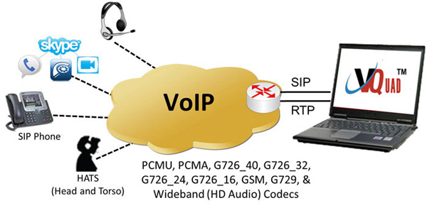
- VQuad™ can be configured to support up to 12 VoIP SIP User Agents
- Testing Analog Telephone Adapters (ATAs)
- Supports outband DTMF/MF digits for RFC4733 and RFC2833.
- Impair outgoing traffic using a noise file or user-defined white noise
- Supports almost all standard Voice Codecs (PCMU, PCMA, G726_40, G726_32, G726_24, G726_16, GSM, G729, and Wideband HD audio codecs).
For more information to voice-codecs webpage.
Resources
Note: PCs which include GL hardware/software require Intel or AMD processors for compliance.
| Item No. | Description |
| VQuad™ Network Options | |
|---|---|
| VQT251 | Dual UTA HD Next generation Dual UTA with FXO Wideband support Accessories USB Cable 2.0 (1) 3.5 mm jack audio cable (2) RJ 11 cable (2) |
| VQT252 | Dual UTA HD – Bluetooth Option |
| VQT253 | E&M Option for Dual UTA HD |
| VQT010 | VQuad™ Software (Stand Alone) |
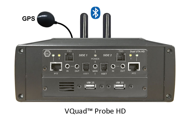
| VQT280 | VQuad™ Probe HD (with Dual UTA HD) Accessories Power Adapter 12V, 3Amps (1) 3.5 mm jack audio cable (2) RJ 11 cable (2) |
| VQT281 | VQuad™ Probe HD w/o Dual UTA HD |
| VQT285 | VQuad™ Probe HD Upgrade |
| Item No. | Related Software |
| VQT013 | VQuad™ with SIP (VoIP) Call Control |
| VQT015 | VQuad™ with T1 E1 Call Control |
| VQT601 | Mobile Device Controller (MDC) Software |
| VQT600 | VQuad™ NetTest Data Server Solution (Requires annual license renewal to remain functional) |
VQT650 |
Video Application Controller (VAC) |
| VQT022 VQT022a |
VQuad™ Fax Emulation (2 simultaneous ports) VQuad™ Fax Emulation (8 simultaneous ports) |
| VBA038 | FaxScan™ for PCM |
| PKV104 | FaxScan™ for SIP and Fax over IP (T.38) |
| VQT442 (cable) | Mobile Audio Interface for Smartphones |
VQT461 (Cable) |
Dual UTA HD Smartphone ACC Cable |
| VQT443 (cable) | 3-wire headset interface Adaptor for Smartphones |
| VQT002 | Voice Quality Testing (PESQ only) |
| VQT006 | VQT w/ POLQA Server license (no limitations) |
| VQT007 | VQT POLQA v3, server license for 20 nodes |
| VBA032 | Near Real-time Voice-band Analyzer |
| EMU037 | Echo Measurement Utility (EMU) Software |
| VQT040 | WebViewer™ |
| Item No. | mTOP™ Solutions |
| MT001 | mTOP™ Rack Mount Enclosure w/SBC (intel core i3) |
| MT001E | mTOP™ Rack Mount Enclosure w/SBC (intel core i7) |
| MT002 | mTOP™ Rack Mount Enclosure w/o SBC |
| MT005 | mTOP™ Probe (Portable Stand-alone) (intel core i3) |
| MT005E | mTOP™ Probe (Portable Stand-alone) (intel core i7) |
| Brochures |
|---|
| Dual UTA HD Brochure |
| VQT POLQA-PESQ Brochure |
| Supported Codecs |
| GL Product Lists |
| Presentations |
|---|
| Voice, Video, Data Quality Testing Presentation |
| Video Application Controller Presentation |
| Quick Install Guide |
|---|
| VQuad Quick Install Guide |
| VQT Quick Install Guide |
| WebViewer and Data Import Quick Install Guide |