Delay Compensation for TDM Networks (T1/E1)
Overview
Often, multiple Radio Frequency (RF) sites receive the same radio transmission from users in remote locations. When two or more RF sites receive the transmission, they will forward the audio streams to a central dispatch location. The operator at dispatch will therefore hear multiple audio streams arriving out of phase, resulting in an echo effect. The audio streams arrive out of phase because each RF site uses independent backhaul networks for transmission. These networks include satellite, microwave and terrestrial (wired) based networks. Typically, satellite networks introduce the most latency and terrestrial networks introduce the least. The echo drastically reduces audio quality and can result in life threatening situations for people in remote locations.
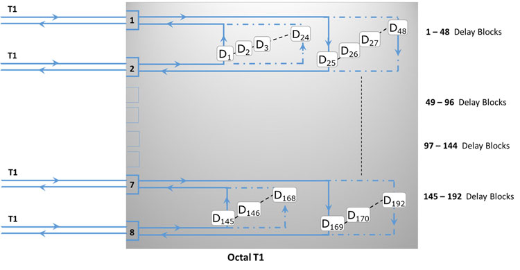
GL Communications has developed an Echo Mitigation System (EMS) which works by aligning the out of phase redundant audio streams. The EMS adds precise delay to the stream that arrives first, so that it aligns with the stream that arrives later. This ensures that the two audio streams are in phase at dispatch and eliminates echo. These delays are added on T1 networks where each stream is carried on a different DS0. A user configurable delay is applied independently to each DS0 in the T1. This solution scales to larger TDM networks as well. For example, GL's Octal Cards have 8 T1 ports. All 192 DS0s (8 T1s * 24 DS0s per T1) can experience different user configurable delays.
Hardware Platform and Specification
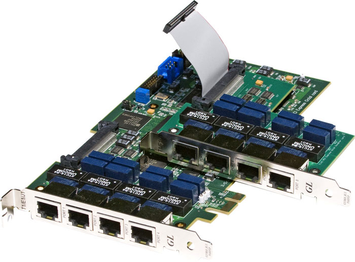
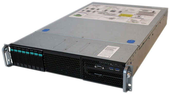
| Octal T1 Card (EMS) | Intel® Server System R2208WT2YS | ||
|---|---|---|---|
|
|
||
Main Board |
7.7” x 4.4” 1xPCIe Connector |
Form Factor |
2U Rack |
Daughter Board |
3.8” x 4.2” Without PC Interface (Occupies 1x PCIe Space) |
Expansion Slots |
1x PCIe x4 Gen 3 |
Theory of Operation
- Initially, a delay measurement is performed.
- A signal (noise) is transmitted towards the remote end point, and with the loopback in place, the signal is returned and measured for delay. The delay measurement is almost instantaneous, but 3 or 4 measurements should suffice to confirm stability.
- Each direction of a duplex T1 is demultiplexed into its individual DS0s. The delay can vary on each DS0. To align these signals at the remote end point, users must determine the difference in the delay values that must be applied to synchronize the signals and then configure these delay compensation values in the EMS software accordingly.
- The EMS software contains a configuration utility through which users specify delay values. The application then allows to simulate the delay values in accordance to the user “configuration file” and then loopback at the remote endpoint.
- The EMS software in Octal T1 board can implement delay compensation for 4 bi-directional DS1s.
- Delay is implemented via a delay buffer scheme with separate delays in transmit and receive directions.
- EMS software translates DS1 and DS0 configuration data into settings appropriate for the T1 hardware. The T1 Configuration should be: ESF Framing, No Loopback, Terminate, Recovered Clock, B8ZS Line Coding, Cross Port Transmit.
- DS0 and DS1 configuration data is retained in a database. Multiple configurations may be saved.
- EMS Software performs round-trip delay measurements. One-Way delay measurement available using companion equipment.
- EMS functionality can be enabled or disabled at both DS1 and DS0 levels.
EMS GUI Features
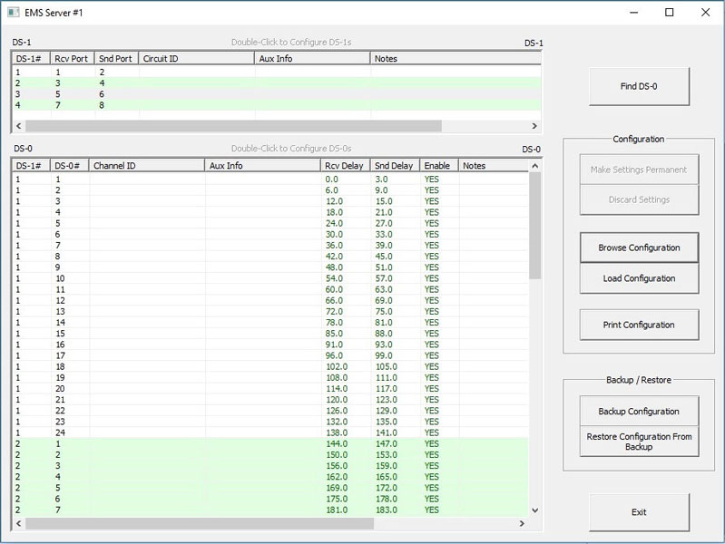
- An Octal T1 Analyzer contains eight (8) ports; four (4) inputs and four (4) outputs for bi-directional connections.
- The EMS software can process 96 DS0 circuits (i.e., four DS1 circuits) per Octal T1 Analyzer. Note: Each of the 96 DS0s can be individually assigned their own delay parameters.
- Maximum of four (4) seconds of delay can be applied on any DS0.
- The system will be able to inject circuit delays without degrading or disrupting communications using the standard timings of 3.0 ms on a D4 format circuit, and 6.0 ms on ESF format.
- The system will be able to add circuit delays independently in the transmitting and receiving paths of a DS0.
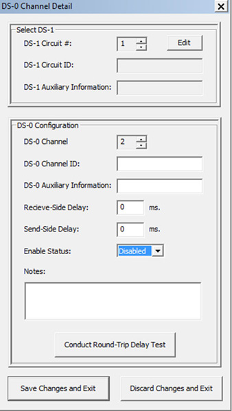
- Each DS-0 configuration provides details such as Channel ID, Auxiliary Information, Receive Side Delay, Send Side Delay, Enable Status, Circuit Enable or Disable, and Notes.
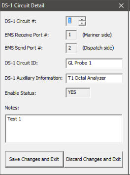
- Each DS-1 has 24 DS-0s. The DS-1 configuration provides details such as Circuit ID, Auxiliary Information, and Notes to the selected DS-1 circuits for circuit identification.
- The system will be able to print all delay values, system and circuit information to a printer.
- When accessing a DS1 field, DS0’s associated with that specific DS1 are shown.
- Channel numbering in the user interface for DS0 assignments will use 1-24 and not 0-23.
- The system will be configurable locally or remotely via the user network
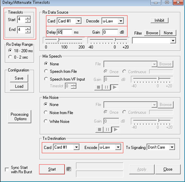
Delay / Attenuate Timeslots
- Allows to apply delay, attenuation, and/or filtering to a received signal on any number of timeslots
- An "input-process-output" application -
- data is retrieved from the Rx Data Source;
- processed by delaying, attenuating, and/or filtering it;
- retransmitting the processed block on the Tx Destination.
- Mix in additional signals from a number of sources, including
- Speech and/or Noise signals from files
- Speech signals inserted via VF input
- Gaussian noise signals generated internally
For more details, visit Delay / Attenuate Timeslots webpage.
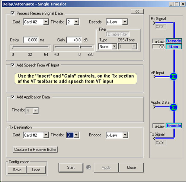
Delay/Attenuate - Single Channel
- Facilitates Low Delay Echo Path Modeling
- Apply delay, attenuation (gain), and/or filtering to a received signal on a single timeslot
- Mix-in additional signals from other sources, Speech signals inserted via VF input and Gaussian noise signals or Tone generated internally
For more details, visit Delay/Attenuate Single Timeslot webpage.
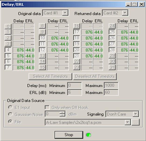
Measure Loop Delay & Echo Return Loss
- Provides the capability to measure and display Loop Delay and Echo Return Loss (ERL) on one or more timeslots.
- Supports two basic modes of operations -
- Non-Intrusive: Two GL boards are used, one of which monitors the original signal while the other monitors the returned or looped-back signal.
- Intrusive: One or two GL boards are used. A signal is injected into one or more timeslots and the returned signal is monitored.
- Multiple instances of this application may be opened simultaneously, allowing measurements to be taken on multiple timeslot ranges and measurement strategies.
For more details, visit ERL Loop Delay webpage.
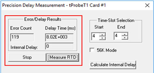
Precision Delay Measurement
- Measures the Round-Trip Delay of a system
- Measurement is precise and accurate to the microsecond level.
- A delay up to 8 seconds can be measured. The internal delay of the card is subtracted from the round-trip delay
For more details, visit Precision Delay Measurement webpage.
Echo Measurement Utility
- Echo Measurement Utility Software (EMU) measures Echo Path Delay (EPD) and Echo Return Loss (ERL) of voice calls.
- Measures EPD in msec and ERL in dB.
- Graphically displays source signal, received signal, error signal, and adaptive filter coefficients.
- Allows zoom-in on each graph, exporting snapshots of these graphs to files for later analysis.
- Compares source and received files to detect maximum of 4 echoes (maximum of four instances).
For more details, visit Echo Measurement Utility webpage.
Delay Measurements
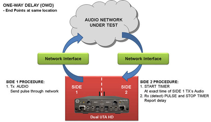
OWD - End points at same location
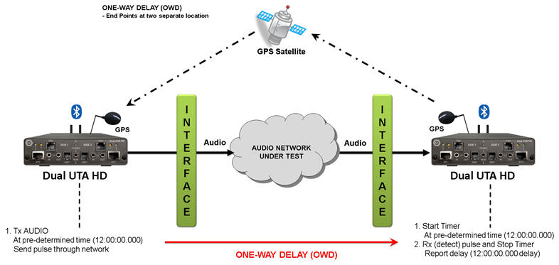
OWD - End points at separate location
- One Way Delay (OWD) - VQuad™ includes an advanced method for performing One Way Delay (OWD) measurements using a Correlator algorithm. The Correlator method is extremely accurate and works with the next generation Dual UTA HD
- Round Trip Delay (RTD) – the new method of measuring RTD using the Correlator algorithm supported on Dual UTA HD
- Post Dial Delay (PDD)
- Signal-to-Noise Ratio (SNR = S/N)
- Oscilloscope and Spectral Display
- RMS Power as well as C-Message
- Audio analysis of any recorded voice file for both Power and Frequency. RMS power and frequency response outputs are necessary for testing the network for full WB voice support.
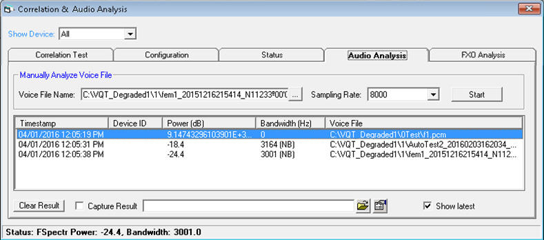
Audio Analysis
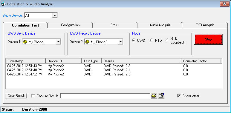
OWD using Correlator
For more details, visit Network Delay Measurements webpage.
T1 E1 Error Insertion & Bulk Delay Application
Bulk delay is an added feature in Error insertion application, that allows users to apply delay on the entire T1/E1 trunk (full multi-frame) of 1.544Mbps (T1) pipe or 2.048 Mbps (E1) pipe. This helps to simulate network delay along the T1E1 links.
- Bulk delay can be applied in either microseconds or milliseconds units
- Delay can be varied from 0 to 169.77mSec or 69 to 169845 µSec for T1 and 0 to 127.99mSec or 46 to 128042µSec for E1 with an accuracy of ±10µSec.
- The delay resolution is based on the byte increments of T1 or E1 (8 bits at a time)
- The bulk delay inserted can be verified using the Precision Delay Measurement application.
For more details, visit T1 E1 Error Insertion & Bulk Delay webpage.
Resource
Please Note: The XX in the Item No. refers to the hardware platform, listed at the bottom of the Buyer's Guide, which the software will be running on. Therefore, XX can either be ETA or EEA (Octal/Quad Boards), PTA or PEA (tProbe™ Units), UTA or UEA (USB Units), HUT or HUE (Universal Cards), and HDT or HDE (HD cards) depending upon the hardware.
| Item No. | Item Description |
| XX003 | Timeslot Delay Loopback for T1 (Currently implemented in Octal T1/E1 Analyzer) |
| XX003 | Timeslot Delay Loopback for E1 (Currently implemented in Octal T1/E1 Analyzer) |
|
Related Software |
|---|---|
| XX063 | Echo Path Delay/Loss Measurement Software |
| XX062 | Echo Path Delay/Loss Simulation Software |
| XX065 | G.168 Echo Canceller Test Suite |
| XX066 | Digital Echo Canceller |
| XX068 | Semi-automated Scripted EC Testing |
| PKB081 | Automated Acoustic Echo Cancellation (AEC) Compliance Test Software |
|
Related Hardware |
| XTE001 XUT001 XUE001 |
Dual T1 E1 Express (PCIe) Boards (requires additional licenses) Dual T1 E1 Express Card Basic T1 Software (includes xx600, xx605) Dual T1 E1 Express Card Basic E1 Software (includes xx600, xx605) |
| FTE001 ETE001 ETA001 EEA001 |
QuadXpress T1E1 Main Board (Quad Port- requires additional licenses) OctalXpress T1E1 Main Board plus Daughter Board (Octal Port- requires additional licenses) Basic Software for T1 (includes xx600, xx605) (zero dollar, but required with appropriate licenses) Basic Software for E1 (includes xx600, xx605) (zero dollar, but required with appropriate licenses) |
| PTE001 PTA001 PEA001 PTE015 PTE025 |
tProbe™ T1 E1 Base Unit tProbe™ Basic T1 Software (includes xx600, xx605) tProbe™ Basic E1 Software (includes xx600, xx605) w/ 2Wire FXO and FXS Optional Board w/Data Communications Board for RS-232, RS-449, RS-422, RS-423, EIA-530, V.35 Interfaces |
| Brochure |
| Echo Mitigation System - Brochure |
| GL Product Lists |
| Presentation |
| Echo Mitigation System - Presentation |