Precision Delay Measurement
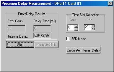
Precision Delay Measurement measures the Round trip Delay of a system. Round trip delay measurement is done by sending a BER pattern with the insertion of an errored bit and timing
the reception of the errored bit. Measurement is precise and accurate to the microsecond level. A delay up to 8 seconds can be measured. The internal delay of the card is subtracted from the round trip delay.
The delay measurement can be made
- For the entire bandwidth or specific timeslots
- DS0 Data Rate for T1 Systems can be set to 56K by checking 56 K Mode. This mode is useful when 'robbed bit signaling' is used in the system
In the Precision Delay Measurement Application, the T1/E1 card transmits a QRSS pattern with an error bit and starts the counter. The BER Pattern gets looped back by an external system or network and the received bit stream is searched for the error bit that was transmitted. Round Trip Delay is calculated as the time difference between the transmission and reception of the error bit.
Time Delay Measurement Theory of Operation:
The time delay measurement is performed in the application Xilinx, using a simple counter to measure the time between the insertion of an errored bit in the transmit data stream, and the recognition of the errored bit in the receive data stream. The Xilinx load is based on the QRSS bit error rate test (BERT) architecture. The serial error readout has been modified to provide a combination of error counter and time delay counter, and the size of the readout has been increased to 32 bits. The first 8 bits are used in the same manner as the standard BERT Xilinx loads. This provides an initial indication of the validity of the incoming data stream, which should be error free. The next 24 bits represent the time delay in basic clock cycles of the master clock for the card type (T1 or E1). This provides a resolution of less than one microsecond, and a timing capacity of almost eight seconds. Errors are inserted (and timing is started) in the same manner as the conventional BERT Xilinx loads - the errored bit is the first bit permitted by the fractional time slot assigners, skipping over bits which are not permitted to be errored (framing bits, signaling bits, etc.). Errors are detected (and timing is stopped) when the corresponding bit position within the frame is detected in the received bit stream.
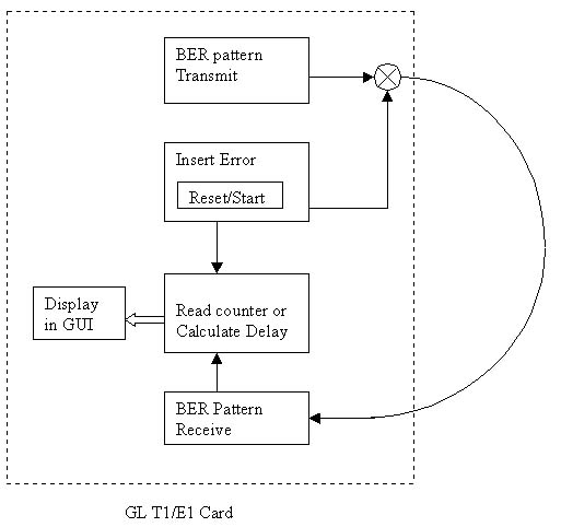
Round Trip Delay Measurement - Working Diagram
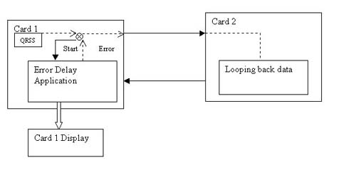
Round Trip Delay Measurement - Application Diagram
 Back to List of T1E1 Basic and Optional Applications Index Page