T1/E1 Call Capture & Analysis Software
Call Capture and Analysis
The Call Capture and Analysis (CCA) application is used to capture calls directly from the T1, E1, and 2-Wire lines.
The application uses GL's T1 E1 Analyzer Hardware Units to interface non-intrusively with T1 or E1 lines.
The Call Capture & Analysis (CCA) application is used to initiate recording of calls, either automatically or manually on both East and West directions simultaneously. The auto scanning provides traffic and signaling based triggers. Signaling triggers supports call capture based on ISDN, SS7, CAS (R1, wink start, MFC-R2) messages. The traffic activated triggers supports call capture based on voice, fax, modem, tones, & any traffic with specified power level.
Subsequently, play back the captured calls using a third party audio editing software tools (Adobe Audition/Goldwave) and analyze in time and spectral modes.
When used in conjunction with Voice Band Analyzer and Call Data Records, the captured signaling and voice can be used to trouble-shoot customer complaints of voice call quality, voiceband data, fax quality, and tones and dual tone transmission issues.
Automatic call capturing can be triggered from both directions (east and west) of transmission.
The call capture application supports following types of triggers for auto capturing of call
- Signaling based triggers - CAS -R1, wink start, MFC-R2
- ISDN and SS7 message based triggers
- Traffic activated triggers
- Voice based on a minimum power level
- Tones of specified frequency - Ring back tone, Dial tone, Busy tone, and DTMF digits
- Fax traffic - V.32 / V.17, V.27, V.29,
- Modem traffic - V.22 forward/reverse channel, V.34 & V.90 uplink, Binary V.90 downlink, FSK
- Any type of signal based on any power level
- Supported codecs data rates are - a-law, µ-law, 16-bit PCM (Intel), 16-bit PCM (Motorola), MS Wave, G.726 (40 Kbps, 32 Kbps, 24 Kbps, and 16 Kbps), and 14-bit 16 KHz G.722 (64 kbps)
Subsequently, captured calls can be played back and analyzed in time and spectral modes using a commercial sound card, built-in high fidelity speakers, and audio viewing software (Adobe Audition, Goldwave).
Frequency, power of east and west directions cannot be shown in real time in CCA application. We can only capture the files. The application also indicates the channels on which a recording is taking place and the files names to which data is being stored. Scanning mode is possible wherein all 24 or 30 channels are scanned for call initiation and recording. A message area provides status of the capture process. Other features include,
Operating Modes |
|
|---|---|
Encoding Formats |
|
Captured Results |
|
Captured File Name Handling |
|
Trigger based Capture |
|
Filters |
|
Auto Signaling Trigger Options |
|
Auto ISDN Trigger & Capture Options |
|
Auto SS7 Trigger & Capture Options |
|
Auto Traffic Activated Capture |
|
Automatic Call triggering can be done in one of the following ways:
- A, B, C, D - Signaling Bits- with user-defined start and stop ABCD signaling bits to initiate and terminate recording of files on chosen timeslots - useful for CAS calls. In addition, CAS signaling such as DTMF digits, MF digits, and MFC-R2 digits conveying "called and calling numbers" are decoded and attached as part of the captured file name.
- Tone - user-defined mono or dual tones can trigger the capturing of a call CCA - useful for fax calls
- Signaling + Tone - a combination of user-defined Start/Stop signaling bits followed by a mono or dual tone (user-defined) within a specified timeout period - useful for capturing fax calls
- ISDN calls - capture gets triggered when any ISDN calls are placed. Called and calling number can be gathered as part of the capture process and attached to the captured file name. During call capture, the following parameters are displayed: ISDN message types, CRV, Time slot, card number, called and calling numbers.
- SS7 calls - SS7 voice calls are kept in CIC groups. When an SS7 call is detected, an Origination Point Code (OPC), a Destination Point Code (DPC), and a CIC # is retrieved. If the comparison holds good capture task is performed, otherwise the call is discarded.
- Traffic activated - With this trigger option, it is possible to trigger on various kinds of traffic such as fax, modem, tones of standard frequency, digits, voice,
and any signal based on power level. Users can also define the traffic algorithms such as linear, quadratic, hybrid, or hybrid filtered that performs the traffic
classification.
Multiple Call Capture and Analysis
GL’s Multi CCA application is similar to CCA, where in it is used to monitor hundreds of calls, capture the bidirectional data, signaling and traffic, simultaneously from multiple T1/E1 lines, based on the user-defined trigger configurations. Once the capture trigger type is selected, users can control and run multiple capture instances on different T1/E1 ports from a single GUI.
Applications of CCA
- Call recording for post analysis
- Analysis of single/dual tones, DTMF and MF digit analysis (frequency, power, duration)
- Analysis of call quality (speech levels, noise levels, echo return loss, speech clipping, impulse noise, and other impairments)
- Call activity, call density, and call volume analysis
- Monitoring and recording Fax, Voice Modem, ISDN, SS7 and CAS calls
- Filtering of calls by "called" and "calling" number
- Listening to finished calls and active calls as they are occurring
- Remote monitoring of calls including remotely listening to calls
GL also provides other various transmission & capture software that helps is call monitoring & analysis over network. Visit Call Signaling and Analysis page for more details.
Operating Modes & other Call Capture Options
- Auto Scanning Capture Mode - Scans timeslots that were checked in "Timeslots" dialog box. The type of scanning that occurs is dependent on the Capture Trigger Type selection. Automatic call capturing can be triggered from both directions (east and west) of transmission.
- Manual Capture Mode - Permits capture manually, irrespective of signaling bits or tone definitions.
- Capture Trigger Types - For auto scanning, ISDN, SS7, CAS (R1, wink start, MFC-R2), and Traffic (voice, fax, modem, tones, & any traffic with specified power level) activated signaling triggers are supported. CCA supports Fax Analysis using GL’s GLInsight™ or GL FaxScan™ applications that analyze the saved PCM files, decode fax image as TIFF files and produce detail call logs.
- Start Trigger Signaling bits - Signaling bits definition for the beginning of capture; must be a transition from the stop trigger to the start trigger
- Stop Trigger Signaling bits - Signaling bit definition for the end of capture; transition not required
- Device Selection - Up to two devices may be selected for capturing or scanning.
- Record Time - In Auto Scanning mode, the duration of the capture can be limited to a certain length by checking Limited Capture and setting the slider control
- Tone Wait - After a signaling trigger, the time (seconds) the application should wait for a defined tone to occur.
- CAS Digit Parsing - The CAS Digit Parser is used to name the call files using the digits that are prefixed to the rest of the filename. By default, this option is disabled, during which, the files are named based on the timestamp and timeslot information, such as Jun15E01_0002.pcm. CCA has five built-in scripts for commonly used protocols - CAS R1 DID*ANI, CAS R1 ANI*DID, CAS R1 DID only, MFR2-176 (CCITT), MFR2-179 (CCITT). It also allows users to select the script of their own choice.
- File Naming Convention - Two different types of file naming conventions are provided based on the capture type for signaling. The file naming conventions are:
Normal - This is the normal mode of capturing data that is prevalent common to both T1 and E1 analyzers.
MFC-R2 - If the CCA application captures data for MFC-R2 signaling type of calls, then this mode has to be enabled. Selecting this option causes a
change in the file naming extension. i.e. *.pcm extension is removed".
Call Capture Options
Call Playback and Viewing Features
Oscilloscope (Time Series) View
For a recorded call, a graph of the amplitude vs. time can be displayed. The display can be for either one side or both sides of the call. Playback, zoom-in, zoom-out, and other options are available for analysis of partial and/or full call data/ Signaling data during call set-up can be analyzed e.g. DTMF/MF, dial and busy tones at microsecond duration granularity. Every sample is recorded and displayed.
There are several methods for viewing captured files supported by various visualization programs such as Adobe Audition and Goldwave programs. Adobe Audition and Goldwave are used with a variety of file formats including PCM, wav, and others. Refer to Adobe Audition and Goldwave User's Guide for detailed instructions or Contact GL Communications Inc for additional details or clarifications about this.
Spectral View
A graph of power level vs. frequency is displayed for the user-selected portion of the recorded call. Users can set the frequency resolution and frequency band of interest. The display can be either one side or both sides of the call. Useful for DTMF/MF, dial, busy tone, speech and modem frequency analysis. Spectrogram displays are also possible.
Goldwave/Adobe Audition
The wave graph of captured files can be visualized using 3rd party audio editing software such as Goldwave or Adobe Audition. The graphical software program should be installed in order to directly invoke captured files through GL's T1E1 analyzer. Goldwave can be used to visualize maximum of two files.
To view stereo wave graph select dual files to view both the graphs simultaneously.
The names of the files chosen for display is merged as one *.wav file. Goldwave uses variety of file formats including *.pcm, A-Law, Mu-Law, *.wav, and others. Any file formats chosen is converted to *.wav while displaying graphs.
Example: For dual file graph display, select "Samp_wst.pcm" and "Samp_est.pcm", a single "Samp_wst_ Samp_est.wav" file is created and the graph is displayed one below the other.
Tabular Analysis
A special DOS application is provided for MFC-R2 digit analysis (r2ana.exe). With this software captured files can be analyzed for R2 tones and signaling. Forward and backward-paired tones are detected and displayed with time stamped indications of digit durations and signaling changes. Call duration, timeslot, date, and time of occurrence are also recorded.
ISDN Call Capture Options with NFAS (Non-Facility Associated Signaling)
CCA is capable of capturing ISDN calls with or without NFAS option. For calls with NFAS, one needs to identify the NFAS interface options (Explicit / Implicit) using the ISDN Analyzer.
The CCA gets triggered when any ISDN calls are placed. Capture occurs after the ISDN message, "SETUP", is detected with the called/calling number that matches the filtering definition for ISDN Call Filtering Options.
CCA can be set to capture the ISDN calls on the trunks that contain D-Channel using options under NFAS. NFAS is a standard option available for ISDN PRI call processing system. This allows a single D channel to control multiple PRI trunks. With NFAS option, a single D-channel can control a maximum of 479 B-channels, i.e., up to 20 trunks (or a maximum of 478 with one B-channel as a backup). In case of GL's Dual T1/E1 Analyzer, a maximum of 95 B-Channels, i.e., up to 4 trunks is supported.
- NFAS D-Channel - Allows to capture ISDN calls with the NFAS signaling
- D-Chan # - Used to specify the T1/E1 trunk that contains the D-Channel or signaling
- Explicit Interface - With this, the CCA is set to capture NFAS calls for the trunks which does not include D-Channel, i.e the calls over NFAS group members. Each group member is identified based on the Explicit interface identifier. All messages are “explicitly defined” with an “interface identifier” of 0,1,2,3,4,5,6,7 depending on which bearer has the traffic
- Implicit Interface - With this, the CCA is set to capture the calls on the trunks containing D-Channel
For more information, refer to ISDN Analyzer.
User will be able to determine the Explicit Interface number based on “Interface Identifier Present” and “Interface Identifier” parameters in ISDN SETUP message as captured in ISDN Analyzer. If the ISDN call is explicit then configure CCA as per the Explicit Interface Number observed in the analyzer.
In NFAS, The trunk which contains the D-Channel can be of Explicit or Implicit interface. If it is an Explicit Interface, normally its Explicit Interface number will be ‘0’. If it is an Implicit Interface, then it does not contain any Explicit Interface number.
SS7 Call Capture Options
SS7 voice calls are kept in CIC groups. When an SS7 call is detected, an Origination Point Code (OPC), a Destination Point Code (DPC), and a CIC # is retrieved. If the comparison holds good capture task is performed, otherwise the call is discarded.
Configure Redundant Data Links
- Data Rate: The possible data rates are 56 or 64 kbps. The SS7 facility data link is a clear channel circuit dedicated to the transmission of SS7 messages. The data rate of this link is commonly 56kbps in ANSI networks and 64 kbps in ITU and other networks. Signaling data links are assigned to an E1/T1 (DS0) timeslot. Not supported is the T1 variant where an entire T1 span is used for signaling.
- Call Filtering: SS7 Call Filtering allows users to search the SS7 call setup Initial Address Message (IAM) to a specific called or calling number. SS7 Call Filtering is similar in functionality to that used in ISDN filtering. Regular expressions such as "*", and "?" can be used. An expression such as "123*" means only call #'s that start with "123" have a possibility of being captured.
- Signaling Links: Signaling links are usually assigned in pairs for redundancy and may or may not be contained in the voice trunks. Links are engineered to carry 40% of the expected load so if a redundant link fails the load would be 80% of capacity. Depending on their locations in the network, links have designations as either A (access), B (bridge), C (cross), D (diagonal), E (extended), or F (fully associated) links. It will take two trunks (cards) to monitor each data link or four trunks (cards) to monitor two data links. CCA allows two sources of signaling to be used, primary and secondary. Each direction of the link is designated as Uplink and Downlink. The port selection for uplink and downlink must be on the same card. Incoming calls are detected on the signaling timeslot. A signaling timeslot cannot also be used for voice data.
- First Card # - Designates the signaling trunk and timeslot used for a primary link. When monitoring a single link designate the connect card (ports) and the timeslot that contains the signaling.
- Second Card # - Designates the signaling trunk and timeslot used for a secondary or redundant link.
- Protocol selection - used to select the appropriate protocol standard being used on the signaling link, such as, ITU, ANSI, ETSI, and China variants are selectable.
- Circuit Group (CIC) Configuration – Bearer traffic is connected between two exchanges with call setup messaging using relative Originating Point Code (OPC) and Destination Point Code (DPC) along with associated Circuit Identifier Codes (ITU 1-4096, ANSI 1-16384) entered with Port Identifications (Card X and Card Y) identifying the signaling trunk and timeslot.
- Device Selection – designates the bearer trunk to be monitored as West and East direction trunks.
- CIC Start – CIC Quantity – Timeslot Start - Timeslots and CICs are generally sequential, although sometimes the timeslot 16 may be skipped e.g. when timeslot 16 is used for framing.
Starting TS identifies where the assignment starts as in some cases a timeslot may be allocated to carry the signaling link. CIC Quantity specifies the number of CICs to assign. - Skip Options - In the E1 protocol, channel 16 is typically used as a signaling channel. CCA now provides the option to map the CICs to the timeslots by either skipping timeslot 16 so it can be used for signaling, or NOT skip channel 16 and map the timeslot to a CIC number. The following options are available regarding skipping:
Both TS 16 and CIC are checked – in this case TS 16 is not used for bearer traffic, and CIC numbering also skips. This means that if TS 15 had CIC as “X”, then TS 17 would have a CIC as “X+2”
Only TS 16 is checked – in this case TS 16 is not used for bearer traffic, but CIC numbering is still consecutive. This means that if TS 15 had CIC as “X”, then TS 17 would have CIC as “X+1”
Nothing is checked – in this case CIC numbering is consecutive
The information below displays examples of how the CIC numbers are mapped to the channel numbers for with and without ‘Skip Timeslot 16’ selections.
Traffic Triggered Call Capture
CCA also includes a feature to trigger capturing of calls based on various types of traffic such as fax, modem, voice, standard tones, digits, and so on. They are V.22 bis forward channel, V.22 bis reverse channel, V.34 & V.90 uplink, V.29, V.32/V.17 > 2400 bps, V.27 ter @ 4800 bps, V.27 ter @ 2400 bps, Voice, binary V.90 downlink, FSK, DTMF digits, Dial tone, Ringback, and Busy tone. Detecting the above types of traffic requires use of the traffic classifier.
A 2048 byte (256 ms) block of data is sent to the traffic classifier. The traffic classifier determines if the data is one of the accepted types of traffic. If the condition is met, then capture of the traffic data commences.
Unlike the other traffic options, triggering on voice traffic can be fine-tuned to the power level of the voice data. Setting the voice power level can be used to filter out weak or undesirable voice data.
Note: CCA requires additional license for traffic activated triggering (XX031).
There is also an option "Any Signal" to be defined in dBm. Selecting this feature bypasses the traffic classifier and detects the power level of the data. If it exceeds the defined input data (e.g. -10dBm), then capture commences.
Stopping Traffic or "Any Signal" Capture
Setting the "Silence Options" slider allows for hang-ups during the capture of traffic or "Any Signal" data. For example, if DTMF traffic is being captured, and then non DTMF data is detected, capture continues until the hang-up time limit set by "Silence Options" is exceeded. If the data reverts back to DTMF, the capture continues as it was before the hang-up.
If the hang-up time limit is 400 milliseconds, only one hang-up is allowed before capture is terminated. Each buffer of data is of size 2048 bytes (256 ms).
Traffic Algorithm
The traffic classifier uses four different algorithms to choose from: Linear, Quadratic, Hybrid, or Hybrid Filtered.
- Linear - This algorithm is quicker to computer
- Quadratic - This gives better accuracy but need more time
- Hybrid (Recommended) - It is a combination of linear and quadratic, and the most reliable
- Hybrid Filtered - This eliminates misclassifications, for example, voice with many periods of silence.
The "Hybrid" is recommended algorithm and is used by default in the Multiple Call Capture.
Digits, Tones, Signaling Triggered Call Capture
User-defined option is available for Tone and Signaling + Tone capture trigger options. This feature allows defining the type of tone(s) that CCA application should detect. The application can only detect single and/or dual tones. Various other options such as Power Threshold, Inter-burst Length Threshold, Absolute Twist Threshold, & S/N ratio can be specified for the tones defined.
Call capture using WCS
GL's Windows Client/Server makes the T1/E1 Analyzer as server and allows performing of typical tasks such as real time recording and transmission to/from files, dtmf/mf/mfcr2 digit detection and generation, bit error rate testing, alarm monitoring, Digital Signal Processing (DSP) operations, DS0 power monitoring, and protocol decoding from multiple client locations.
GL's CAS simulator is a client-side application that works along with the GL's T1/E1 Analyzer. It can simulate and analyze any user user-defined CAS protocols by providing signaling bit transitions and forward/backward frequency tones/digits. In addition to generating/receiving CAS calls, the CAS simulator also processes the receipt of Dialed Number Identification Service (DNIS) and Automatic Number Identification (ANI) information. Supported protocols include E1 MFCR2, T1 Winkstart, T1 Loopstart and Groundstart, E1 European Digital CAS, and any User-defined CAS.
Visit following webpages for more information
- Client Server for T1/E1 Analysis Cards
- Scripted DSP Capability
- Channel Associated Signaling Simulator
CCA with other GL applications
- The application works with CCA (Call Capture and Analysis) and VBA (Voice Band Analyzer) applications and generates Call Summary and Call Detail reports. CDR provides comprehensive information on each and every call occurring on T1 E1 lines, including voice capture, signaling information for CAS, ISDN, MFC-R2, SS7, all alarms and errors occurring during the call, detailed voiceband event information (dual tones, fax tones, modem signals, and more), detailed analysis of the voiceband call including noise level, speech level, speech activity factor, echo measurements, and more. It also categorizes call as voice, fax, modem, or data.
- The Near Real-time Voice-band Analyzer (VBA) is an analysis tool for monitoring voice band network traffic. The VBA can host different analysis modules for monitoring speech and noise levels, line echo. VBA operates in near-real-time, processing the signal files recorded by CCA. VBA records its output into two files, the first containing overall channel measurements, and the second containing event records.
- The captured files containing fax and modem information can be analyzed using GL Insight™ Modem and Fax Analysis Software for 2-wire Analog interface.
- The captured files containing fax and modem information can be analyzed using FaxScan™ application to provide analysis of the T.38 packets, T.30 frames, decode a Fax TIF image, and general call-flow indicators for detail analysis.
Near Real-Time Voice Band Analyzer
Additional Sample Screens:
- Call Capture Analysis Main Menu
- Call Capture Analysis Configuration Tab
- Call Capture Analysis Timeslots Tab
- Call Capture Analysis ISDN Options Tab
- Call Capture Analysis SS7 Option Tab
- Call Capture Analysis User Defined Tab
- Call Capture Analysis Tone Detection Parameters Tab
- Call Capture Analysis Traffic Options Tab
- Call Capture Call Storage Options Tab
- Time Series Display
- Spectrum Display
Call View Screens
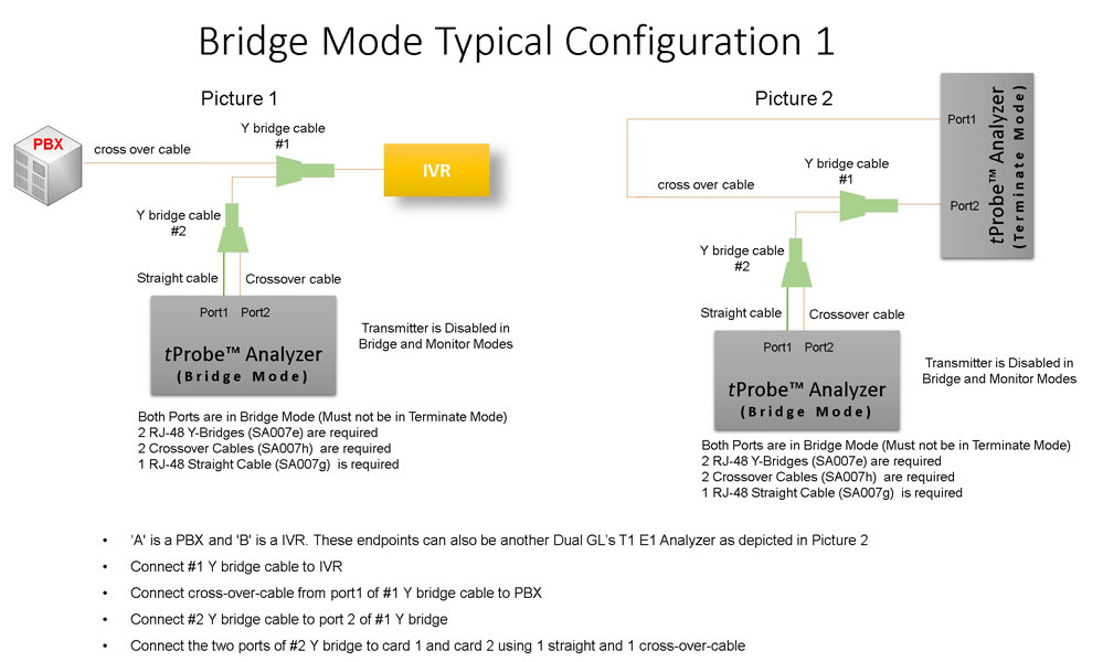
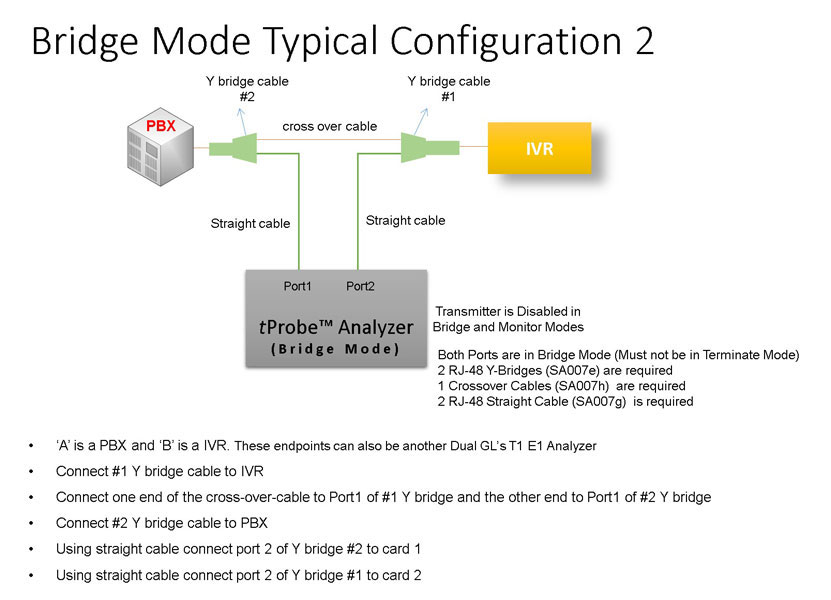
Bridge and Monitor Connections
- Monitor from a DSX-Patch Panel
- Bridge Mode Connections for Monitoring T1/E1 Signals for RJ-45
- Bridge Mode Connections Alternative Method
- RJ-45 Connections
Resources
Note: PCs which include GL hardware/software require Intel or AMD processors for compliance.
Please Note: The XX in the Item No. refers to the hardware platform, listed at the bottom of the Buyer's Guide, which the software will be running on.Therefore, XX can either be HDT, HDE, HUT, HUE, UTA or UEA depending upon the hardware.
 Back to List of T1E1 Basic and Optional Applications Index Page