LightSpeed1000™ (Legacy)
Discover the LightSpeed1000™ card for OC-3/OC-12 analysis and emulation, offering wire-speed processing and comprehensive testing capabilities for ATM and PoS protocols
Request a Demo / QuoteUnChannelized - Brochure Channelized - Brochure
Overview
Voice, data, and video traffic is exploding as smartphones, IP TV, video streaming, and "cloud" based services takeoff. A majority of the backbone transport for these applications continues to be SONET and SDH optical transmission networks. A dominant protocol for IP transport is PoS (Packet over SONET) and another is ATM (Asynchronous Transfer Mode). Both schemes are packet based, with ATM using fixed size packets of 53 bytes called "cells", and PoS using variable packet sizes closely matching to Ethernet frames.
SONET and SDH transmission network also continue to be used for conventional channelized traffic – carrying many TDM T1, E1, T3, and E3 pipes.
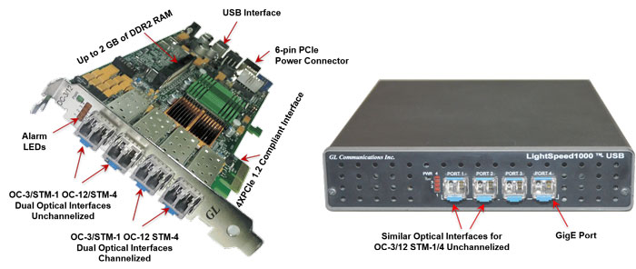
GL's LightSpeed1000™ hardware platform (PCIe Card and USB Pod) is capable of OC-3/12 and STM-1/4 wire-speed processing on quad optical ports for functions such as wire-speed recording and wire-speed playback of Unchannelized and Channelized ATM, PoS, and RAW Traffic.
Two ports out of the 4 ports are meant for SONET/SDH unchannelized and unframed data. The remaining two ports are meant for SONET/SDH channelized data of carrying many independent unframed/framed T1, E1, T3, and E3 streams.
The LightSpeed1000™ comes with software for overall monitoring, BERT, emulation, and protocol analysis with a price tag that compares very favorably with similar test instruments at three times the price.
In an OC-3/STM-1, all 84 T1s or all 63 E1s can be identified and processed in transmit and receive modes. In an OC-12/STM-4, all 336 T1s or all 252 E1s can be identified and processed in transmit and receive modes. The hardware can also be easily configured / programmed for delaying of ATM Cells or PPP packets.
GL Communications has the following variants of OC-3/STM-1 and OC-12/STM-4 Analyzers:
- Quad OC-3/STM-1 and OC-12/STM-4 PCI-Express card (Windows® 7 and above 32-bit, 64-bit)
- Portable Quad OC-3/STM-1 and OC-12/STM-4 Unit (Windows® 7 and above 32-bit, 64-bit)
The card's multiple connectivity using PCIe, Gigabit Ethernet (GigE), USB 2.0 and onboard DDR2 memory makes it suitable for many applications.

Multiple cards are possible in a PC for analysis of four or more directions simultaneously. USB 2.0 interface is used to connect with a Notebook PC for portability. GigE Ethernet ports for testing RAW, BER, RFC 2544, RAW SONET/SDH, and Ethernet bridge applications. The hardware is FPGA based making it easy to upgrade in the field for application versatility.
A unique feature of the unit is the capability to capture, transmit and process at wirespeed to/from applications on all interfaces. An API Toolkit allows users to develop specialized applications.
In addition to LightSpeed1000™ hardware platforms (PCIe Card and USB Pod), GL also offers high-density mTOP™ rack and stand-alone mTOP™ Probe hardware variants. mTOP™1U/2U rack mount enclosures within which LightSpeed1000™ USB units are stacked to provide high density form factor solution for testing Optical/Ethernet network conditions. It is a perfect OC-3/STM-1 and OC-12/STM-4 test tool for customers who require multi-port testing but are constrained by lab space.
And the latest mTOP™ Probe hardware platform is an all-in-one self-contained test instrument which includes a single LightSpeed1000™ USB device combined with the PC interfaces in one single box. The comprehensive mTOP™ Probe hardware unit is designed for easier portability and convenient for field testing.. For more details on mTOP™ test platforms, refer to Test Tools in Rack Based and Stand-alone Platforms.
ATM Analyzer Main Screen with Alarms and Error Monitor Display
PoS Analyzer Main Screen with Alarms and Error Monitor Display
Main Features
- Wirespeed processing of ATM, PoS or RAW data for Tx and Rx for both ports (*PCIe card only).
- Software selectable OC-3 / OC-12, or STM-1 / STM-4 for Unchannelized ATM, PoS or Transparent Traffic, and Channelized T1, E1, T3, E3 traffic.
- Ability to capture/playback to/from disk at full rate in both directions for all ports. This permits detailed offline analysis that is not possible otherwise. Simultaneous synchronous capture is possible on all optical ports. The captured files can be played back to reproduce the traffic.
- Comprehensive transmit/receive testing capabilities; transmitting and verifying data with incrementing sequence numbers with each packet/cell
- Industry proven Protocol Analyzer for Unchannelized ATM (AAL2, AAL5), UMTS, and PPP (IP and higher layer protocols) stream, and Channelized protocols such as ISDN, SS7, CAS, and more.
- Easy to use and flexible Bit Error Rate Test (BERT) application for ATM, POS, and RAW
- Complex and flexible hardware based filtering options: sixteen 128 bit independently filters with bit masks, for both ports with AND/OR include/exclude conditions
- Hardware based precise time stamping of cells / packets with 10 nsec resolution, 1 ppm accuracy
- Single mode or multi-mode fiber SFP support
- High performance x4 PCIe interface with optimized DMA to perform Rx and Tx packets to/from PC memory
- Precisely emulates packet delays that occur over SONET/SDH carrying ATM or PoS traffic, delay is adjustable from 1 ms to maximum of 500 mSec (*PCIe card only).
- Flexible DMA circular buffer architecture to read and write cells and packets at wire-speed
- Multiple cards per system for super high capacity monitoring and test system (*PCIe card only).
- API Toolkit to develop user specific applications
- Optional onboard SODIMM memory (DDR2) – up to 2 Giga bytes
- Hardware independent of higher level protocol for easy adaptation of future protocols
- Field upgradable firmware
- Supports Windows® and Linux operating systems
Packet over SONET / SDH (PoS)
PoS, or Packet over SONET / SDH - OC-3/ STM-1 and OC-12 / STM-4 is supported at full rates. Access, capture, analysis, and emulation of PPP and HDLC, all carrying IP traffic in real-time makes this card useful to many applications including Routing, Deep Packet Inspection, and other Internet traffic applications. Current PoS applications include:
- PoS Protocol Analysis PPP Analyzer can be used to capture a host of PPP protocols
exchanged between the two nodes over SONET/SDH link. User can obtain detailed analysis of higher later protocols (IP, TCP, UDP, HTTP, FTP, POP3 etc) and
can perform various statistics measurements. Integrated Packet Data Analysis feature in Real-time PPP Analyzer is an outstanding tool for live monitoring of
VoIP traffic. It can segregate IP traffic into SIP / H323 / Megaco / MGCP calls and collects statistics, CDRs, detailed protocol traces, ladder diagrams, and a host
of other useful information about VoIP calls. For more information, refer to Packet Data Analysis in MLPPP webpage for more details.
- PoS Tx / Rx Test - This application is an emulation and test tool that transmits fixed, random, or variable lengths test packets and checks packets on receive at a user specified data transmission rate.
- Wirespeed capture of PoS packets to hard disk on both ports simultaneously; with filtering
and time stamping of packets. All packets are captured into GL''s file format for further processing. Offline utility can convert it into GL's HDL file format or PCAP
format. User can also develop application to process the captured file.
- Multiple Versatile filters (ex PPP, IP, UDP etc) can be applied to incoming traffic to allow only traffic of interest.
- Transmit Packets from File - Allows to playback already captured data file to recreate traffic
in controlled environment. Also user created traffic file can be played back to generate user traffic.
- PoS BERT - supports the following PRBS Patterns: 29- 1, 211- 1,
215-1, 220- 1, 223- 1, 229- 1, 231- 1, all one's, all zero's, alternate ones and
zeros, user-defined pattern of lengths from 2 to 32 bits, invert and non-invert selections, single bit error insertion, error insert rate from 10-1 to 10-9, status for pattern sync, bit error counters, packet rate and packet gap configuration options, configurable header lengths and header
information
- Alarms and error (section, path, and line) monitoring and logging.
- Network Delay Emulator - The Network Delay Emulator application provides full duplex delay simulation for PoS and ATM based traffic from 1 ms to 500 ms, with incremental delays of 1 ms. The application combines hardware and software based functions to achieve precision and flexibility. It can emulate packet delays that occur over SONET/SDH carrying ATM/PoS traffic
For more details, visit LightSpeed1000™ POS Analyzer webpage.
Asynchronous Transfer Mode(ATM)
ATM over SONT/SDH - OC-3/ STM-1 OC-12 / STM-4 is supported at full rates. Access, capture, analysis, and emulation of ATM cells at wire-speed make this interface capability applicable for wide ranging next generation networks. Current ATM applications include
- ATM Protocol Analysis ATM Analyzer is used to analyze and view ATM protocols across the U-plane for both NNI and UNI interface carrying AAL0, AAL2 and AAL5 traffic.
- UMTS Protocol Analysis UMTS analyzer is capable of capturing, decoding and performing various test measurements across various interfaces i.e. Iub, Iur, IuCS and IuPS interfaces of the UMTS network. In addition, it supports ATM as the transport layer. It helps in fault diagnosis and troubleshooting UMTS network.
- ATM Tx / Rx Test - an emulation and test capability that transmits ATM test cells and/or analyzes the received cells at a user specified data transmission rate.
- Wirespeed capture of ATM packets to hard disk on both ports simultaneously; With filtering and time stamping of packets. All packets are captured into GL's file format for further processing. Offline utility can convert it into GL's HDL file format or PCAP format. User can also develop application to process the captured file.
- Multiple Versatile filters (VPI, VCI, User Data etc) can be applied to incoming traffic to allow only traffic of interest.
- Transmit Packets from File -to playback already captured data file to recreate traffic in controlled environment. Also user created traffic file can be played back to generate user traffic.
- ATM BERT - support for industry standard PRBS Patterns: 29- 1, 211- 1,
215- 1, 220- 1, 223- 1, 229- 1,
231- 1, all one's, all zero's, alternate ones and zeros, user-defined pattern of lengths from 2 to 32 bits, invert and non-invert selections, single bit error insertion, error insert rate from 10-1 to 10-9. HEC error insertion, on receive filtering is provided for idle cells, GFC, VPI, VCI, CL, and PT cells, statistical details for total cells, valid cells, idle cells, filtered cells, and filtered out cells - Alarms and error (section, path, and line) monitoring and logging
- Network Delay Emulator - The Network Delay Emulator application provides full duplex delay simulation for PoS and ATM based traffic from 1 ms to 500 ms, with incremental delays of 1 ms. The application combines hardware and software based functions to achieve precision and flexibility. It can emulate packet delays that occur over SONET/SDH carrying ATM/PoS traffic.
For more details, visit LightSpeed1000™ ATM Analyzer webpage.
SONET/SDH RAW (or Transparent) Payload
RAW mode captures or playbacks anything and everything on SONET/SDH. This mode allows capturing/replaying including SONET/SDH Framing and payload. Here payload can be anything, including structured traffic (T1, E1, STS-1, DS3 etc) or unstructured traffic (ATM, PoS, GFP etc). Raw or transparent mode allows direct access to the SONET / SDH payload for BERT, data transmit and receive applications. Current applications include:
- RAW BERT - support for the following PRBS Patterns: 29- 1, 211- 1,
215- 1, 220- 1, 223- 1, 229- 1, 231- 1, all one's, all zero's, alternate ones and zeros,
user-defined pattern of lengths from 2 to 32 bits, invert and non-invert selections, single bit error insertion, error insert rate from 10-1 to
10-9, status for pattern sync, and bit errors counters
- Wirespeed capture of raw data to hard disk on both ports simultaneously. The data is recorded
in 64 bytes block with appropriate header.
- Playback of recorded data from file at wirespeed on one or both ports.
- Alarms and Error monitoring and logging at SONET/SDH level.
- Network Delay Emulator - The Network Delay Emulator application provides full duplex delay simulation for PoS and ATM based traffic from 1 ms to 500 ms, with incremental delays of 1 ms. The application combines hardware and software based functions to achieve precision and flexibility. It can emulate packet delays that occur over SONET/SDH carrying ATM/PoS traffic. This mode is applicable only for Applicable only for PCI express based cards.
LightSpeed1000™ - High Density mTOP™ Solution
GL also offers rack-based variant using mTOP™ 1U/2U rack mount enclosures within which LightSpeed1000™ USB units are stacked to provide high density form factor solution for testing network conditions. This multi-device hardware unit incorporates all the features of a portable LightSpeed1000™ unit along with the necessary PC hardware with Windows® OS and remote accessibility via Ethernet Remote Desktop. It is a perfect OC-3/STM-1 and OC-12/STM-4 test tool for customers who require multi-port testing but are constrained by lab space. For more details on mTOP™ rack-based platform, refer to Test Tools in Rack Based Platforms.
LightSpeed1000 mTOP™ Test Platforms - Brochure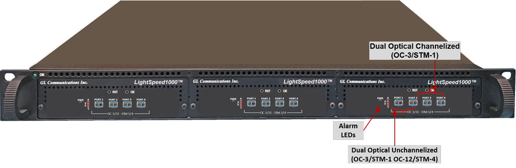
1U mTOP™ with 3x LTS1000 USB units
(MT001/MT001E + LTS1000)
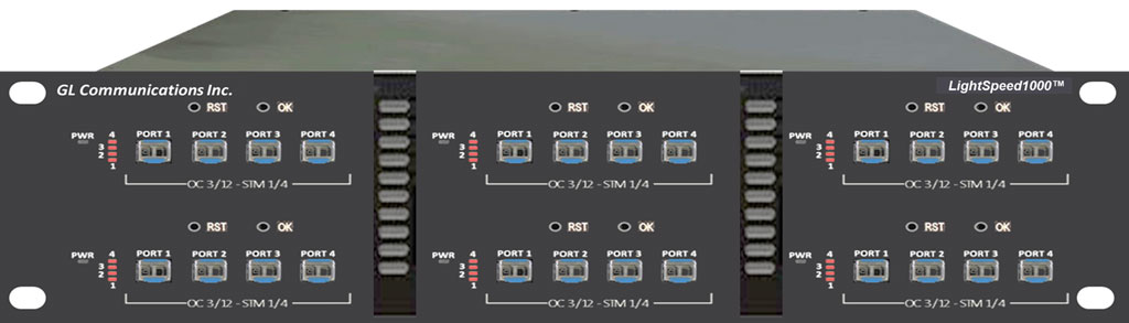
2U Rackmount with 6x LTS1000 USB units
(LTS1000)
| Hardware Specifications | |
Interfaces |
|
Embedded PC Specifications |
1U mTOP™ SBC Specification
2U mTOP™ SBC Specification
|
External Power Supply |
|
Physical Specifications |
|
LightSpeed1000™ mTOP™ Probe
optical interfaces. mTOP™Probe unit which includes necessary SBC making it suitable for field testing. It is a perfect optical test tool for customers who require portable and remote accessibility.
LightSpeed1000™hardware platform is capable of OC-3/12 and STM-1/4 wire-speed processing on quad optical ports for functions such as wire-speed recording and wire-speed playback of Unchannelized and Channelized ATM, PoS, and RAW Traffic.
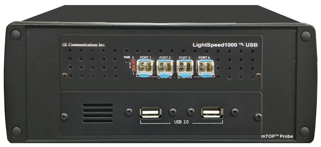
mTOP™ Probe with LightSpeed1000™
(Front Panel View)
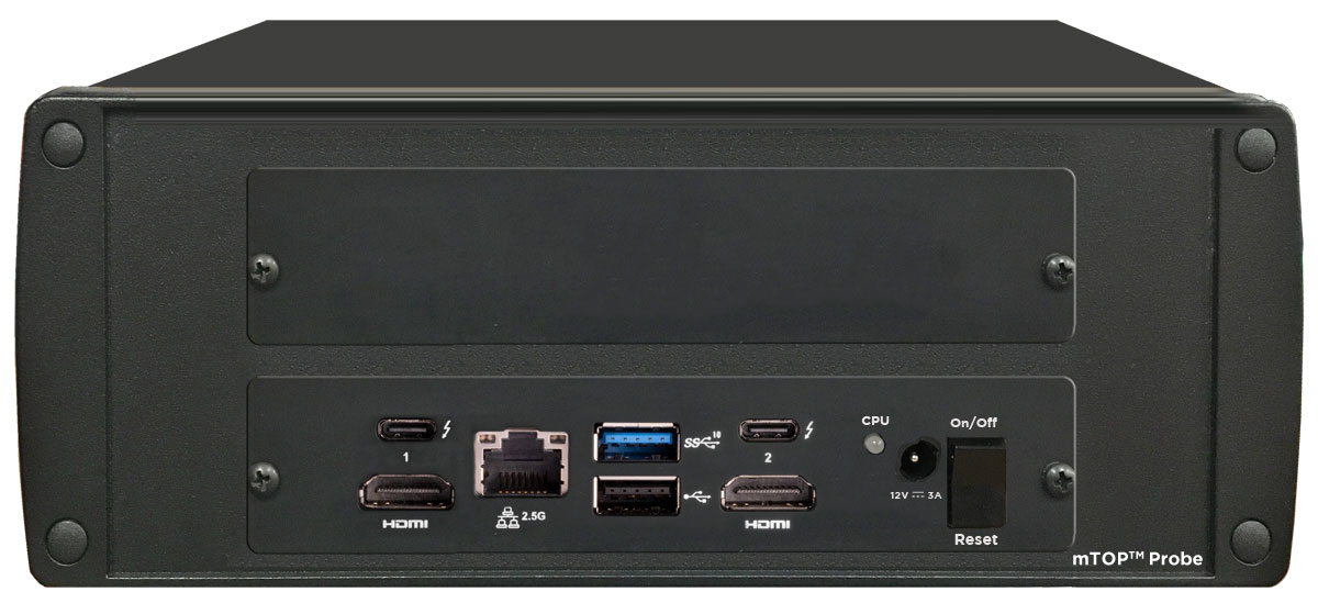
mTOP™ Probe with LightSpeed1000™
(Rear Panel View)
|
LightSpeed1000™ - Specifications
Interfaces: |
|
|||||||||||||||
Alarm LEDs: |
|
|||||||||||||||
Bus Interface: |
|
|||||||||||||||
Power and Dimensions: |
|
|||||||||||||||
Traffic |
|
|||||||||||||||
Regulatory and Compliance |
|
|||||||||||||||
Channelized Protocols (Structured) |
|
|||||||||||||||
| Channelized File based High Throughput HDLC Record/Playback (HdlcHpio) | Below table shows number of channels supported by Channelized HDLC High Throughput Record/Playback application.
|
|||||||||||||||
| Channelized Multi-Channel HDLC Emulation and Analysis (HDLCTerr) | Below table shows number of channels supported by Channelized HDLC Emulation and Analysis application.
|
|||||||||||||||
UnChannelized Protocols (Unstructured) |
|
|||||||||||||||
Clock |
|
|||||||||||||||
Functional Specifications |
Support for Channelized OC3 to T1, Channelized STM1 to E1, full, fractional, or channelized T1/E1 Up to 84 T1 per port (or 2* 84 = 168 T1s per card) Up to 63 E1 per port (or 2* 63 = 126 E1s per card) SONET multiplexing: OC3 -> STS-3 -> STS-1 -> VTG -> VT1.5 -> T1 -> N x DS-0 OC3 -> STS-3 -> STS-1 -> VTG -> VT2-> E1 -> N x DS-0 SDH multiplexing: STM1 -> AUG -> AU-4 -> VC-4 -> TUG-3 -> TUG-2 -> TU-12 -> VC-12 -> E1 STM1 -> AUG -> AU-4 -> VC-4 -> TUG-3 -> TUG-2 -> TU-11 -> VC-11 -> T1 STM1 -> AUG --> AU-3 -> VC-3 --> TUG-2 --> TU-12 -> VC-12 --> E1 STM1 -> AUG --> AU-3 -> VC-3 --> TUG-2 --> TU-11 -> VC-11 --> T1 |
|||||||||||||||
Physical Layer Alarms and Error Counts |
On SONET and SDH
T1/E1 |
|||||||||||||||
Loopback Capabilities |
|
|||||||||||||||
Monitoring Applications |
For T1/E1
On SONET and SDH
|
|||||||||||||||
Intrusive Test Applications |
For T1/E1
|
Resource
| Item No | Item Description |
| LTS100 | Lightspeed1000™ - OC3/12 STM1/4 PCIe Card (Legacy) Accessories PCIe 2x fans (1) |
| LTS105 | Lightspeed1000™ - Portable OC3/12 STM1/4 USB Unit (Legacy)
Accessories USB Cable 2.0 (portable only) (1) 12 V Power Adapter (1) |
| Unchannelized Analysis and Emulation Applications | |
|---|---|
| LTS200 | OC-3 / STM-1 ATM Monitor, BERT, Tx/Rx Test, RAW |
| LTS300 | OC-12 / STM-4 ATM Monitor, BERT, Tx/Rx Test |
| LTS201 | OC-3 / STM-1 PoS Monitor, BERT, Tx/Rx Test, RAW |
| LTS301 | OC-12 / STM-4 PoS Monitor, BERT, Tx/Rx Test |
| LTS202 | OC-3 / STM-1 ATM and RAW Record / Playback |
| LTS302 | OC-12 / STM-4 ATM and RAW Record / Playback |
| LTS203 | OC-3 / STM-1 PoS and RAW Record / Playback |
| LTS303 | OC-12 / STM-4 PoS and RAW Record / Playback |
| LTS204 | OC-3 / STM-1 ATM Protocol Analysis |
| LTS304 | OC-12 / STM-4 ATM Protocol Analysis |
| LTS205 | OC-3 / STM-1 PoS Protocol Analysis |
| LTS215 | Packet Data Analysis (PDA) for PoS OC3 / STM1 |
| LTS305 | OC-12 / STM-4 PoS Protocol Analysis |
| LTS315 | Packet Data Analysis (PDA) for PoS OC12 / STM4 |
| LTS206 | OC-3 / STM-1 UMTS Protocol Analysis |
LTS216 |
Packet Data Analysis (PDA) UMTS OC3 / STM1 |
| LTS306 | OC-12 / STM-4 UMTS Protocol Analysis |
| LTS316 | Packet Data Analysis (PDA) UMTS OC3 / STM1 |
| LTS207 | Delay Emulation for OC3 / STM1 PoS payloads |
| LTS307 | Delay Emulation for OC12 / STM4 PoS payloads |
| LTS208 | Delay Emulation for OC3 / STM1 ATM payloads |
LTS209 |
|
| LTS308 | Delay Emulation for OC12 / STM4 ATM payloads |
| Item No. | mTOP™ Solutions |
| MT001 | mTOP™ Rack Mount Enclosure w/SBC (intel core i3) |
| MT001E | mTOP™ Rack Mount Enclosure w/SBC (intel core i7) |
| MT002 | mTOP™ Rack Mount Enclosure w/o SBC |
| MT005 | mTOP™ Probe (Portable Stand-alone) (intel core i3) |
| MT005E | mTOP™ Probe (Portable Stand-alone) (intel core i7) |
| Channelized Analysis and Emulation Applications | |
| LTS501 LTS502 |
Basic Capability to Rx/Tx RAW OC3 / STM1 Basic Capability to Rx/Tx RAW OC12 / STM4 |
| LTS503 LTS504 |
Record Playback RAW OC3 / STM1 Record Playback RAW OC12 / STM4 |
LTS108 |
Any 16 Ports Chan Lic for OC3/12, STM1/4, n=1 |
| LTEXXX LTTXXX |
Channelized Options for E1(ISDN, SS7, HDLC) Channelized Options for T1 (ISDN, SS7, HDLC) |
| Related Accessories and Cables | |
| IPN1310a | SFP Transceiver for OC-3/STM-1 and OC-12/STM-4 Optical, LC, Single-Mode, 1310nm |
| IPN850a | SFP Transceiver for OC-3/STM-1 and OC-12/STM-4 Optical, LC, Multi-Mode, 850 nm or 1310 nm |
SA019a |
1 Gbps / 10 Gbps Fiber Optic Cable, Single-Mode, Duplex LC to Duplex LC |
| SA019st | Fiber Optic T-tap, Duplex LC, Single-Mode; includes one SA019a; requires one SA019sc |
| SA019sc | Fiber Optic Analyzer Cable (Special ’Y’ Cable), Single-Mode, Duplex LC to Dual Duplex LC, 3m, Special Analyzer Cable for use with SA019st |
| SA019mt | Fiber Optic T-tap, Duplex LC, Multi-Mode; includes one SA019c; requires one SA019mc |
| SA019mc | Fiber Optic Analyzer Cable (Special ’Y’ Cable), Multi-Mode, Duplex LC to Dual Duplex LC, 3m, Special Analyzer Cable for use with SA019mt |
| SA019ska | 1GB Fiber Optic Single-Mode T-tap Kit with Required Cables and SFP Transceivers |
| SA019mka | 1GB Fiber Optic Multi-Mode T-tap Kit with Required Cables and SFP Transceivers |