Overview
The HDLC protocol is a data link layer used for transmitting data between called nodes. The HDLC protocol embeds information in a data frame that allows devices to control data flow and correct errors. A frame of data is encapsulated by flags. The beginning and end of an HDLC frame are marked by flag characters - 01111110 binary.
At the end of the frame, a Frame Check Sequence (FCS) is used to verify the data integrity. The FCS is a CRC calculated using polynomial x16 + x12 + x5 + 1 (FCS 16 bits) or x0 + x1 + x2 + x4 + x5 + x7 + x8 + x10 + x11 + x12 + x16 + x22 + x23 + x26 + x32 (FCS 32 bits).
Idle periods in the data stream contain only flags.
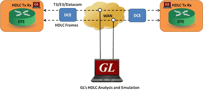
GL's T3 E3/Datacom HDLC protocol analyzer provides the capability to capture, and analyze HDLC data on a T3 E3/Datacom lines. There may be a single data channel per T3 E3/Datacom line. After setting the T3 E3/Datacom ports and FCS type and starting the decoding process, the main screen displays the captured HDLC frames. Flags are stripped, and all other data is presented, including FCS bytes.
In addition to HDLC Analyzer, T3 E3/Datacom analyzer supports HDLC Tx Rx Test application that further helps in transmitting and capturing pre-defined HDLC frames.
HDLC Analyzer Main Features
| Display Features |
|
| Supported Protocols | LAPF, LAPD, LAPD+IP, LAPX+IP, X.25, Cisco HDLC Protocols |
| Filtering and Search | Advanced filtering and search based on any user selected protocol fields |
| Capturing Streams | Streams can be captured on the selected ports |
| Export Options |
|
| Record/Playback |
|
| Remote Monitoring | Remote monitoring capability using GL's Network Surveillance System |
Supported Protocols
Following is a description of the protocols supported by GL's HDLC analyzer:
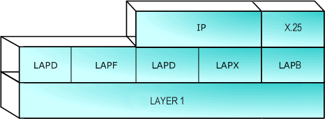
Supported Protocols Structure for HDLC Protocol Analysis
| Supported Protocols | Specification Used |
|---|---|
| LAPD | CCITT Q.920/921 |
| LAPF | ITU-T Q.922 |
| IP | RFC 791 |
| TCP | RFC 793 |
| UDP | RFC 768 |
| ICMP | RFC 792 |
| STUN | RFC 3489 |
| DNS | RFC 1035 |
| DHCP | RFC 1533, 2131 |
| HTTP | RFC 2616 |
| FTP | RFC 959 |
| SNMP | RFC 1157,1155,1902,3416,2863,2578,3418,2011,2012 etc |
| LAPB, X.25 | ITU-T Recommendation X.25 |
| Cisco HDLC | - |
| ARP | RFC 826 |
Summary, Detail and Hexdump Views
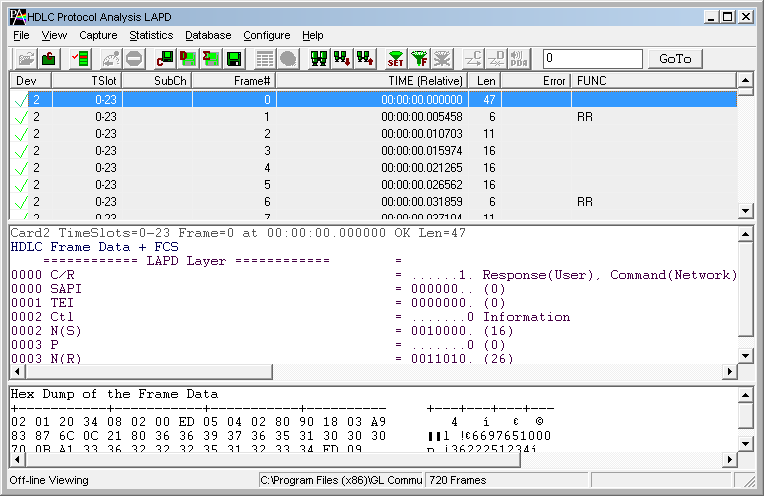
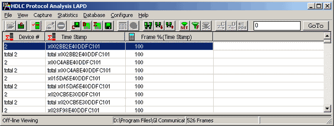
The HDLC analyzer application is invoked from the main menu of GL's T3 E3/Datacom Analyzer for real-time analyzer. The analyzer displays summary, detail and hex dump view in different panes. The summary pane displays Frame Number, Time, Length, Error, C/R, SAPI, TEI, CTL, P/F, N(S), N(R), FUNC etc. User can select a frame in summary view to analyze and decode each frame in the detail view. The selected frame is analyzed and decoded according to HDLC frame specifications. The Hex dump view displays the frame information in HEX and ASCII.
Real-time and Offline Analysis
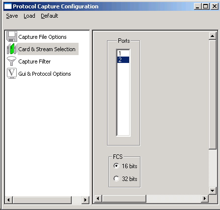
Users can capture and analyze multiple HDLC links in real-time and record all or filtered traffic into a trace file. The recorded trace file can then be analyzed offline and exported to ASCII file, or printed. Real-time capturing requires user to specify Tx/Rx ports FCS (16 & 32 bits).
Filtering and Search
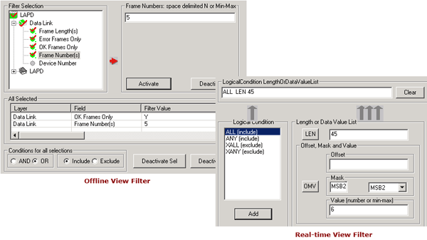
Users can record all or filtered traffic into a trace file. Filtering and search capability adds as another powerful feature to the HDLC Analyzer. This feature can isolate required frames from all frames in real-time as well as off-line. Users can specify custom values for frame length to filter frames during real-time capture. The frames can also be filtered after completion of capture according to CTL, C/R, Modifier Function, N(R), N(S), P, P/ F, SAPI, Supervisory function and TEI. Similarly, search capability helps user to search for a particular frame based on specific search criteria.
Statistics View
Statistics is an important feature available in HDLC analyzer and can be obtained for all frames both in real-time as well as offline mode. Numerous statistics can be obtained to study the performance and trend in the HDLC network and it is based on protocol fields and different parameters e.g. Use Type (Key/Total/Field), Statistic type (Frame count, Byte count, Frames/Sec) and patterns like Range List, Wild card etc.
Enhanced Trace Saving Options
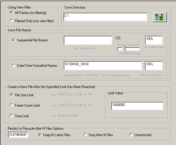
Users can control the captured trace files by saving the trace using different conventions such as trace files with user-defined prefixes, trace file with date-time prefixes, and slider control to indicate the total number of files, file size, frame count, or time limit. This feature also allows the captured frames to be saved into a trace file based on the filtering criteria set using display filter feature
HDLC Test Application
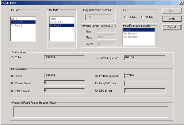
USB T3 E3 HDLC Test Optional Application is designed to transmit and receive HDLC frames over unstructured T3 E3. It generates frames in memory and fills them with 64 bit sequential integer numbers. The number is either truncated if the frame length is less than 8 bytes or the same number bytes are concatenated to make up the complete frame
At the end of each frame a Frame Check Sequence (FCS) is generated to verify the data integrity on the receive side. The FCS (also knows and cyclic redundancy check CRC) is calculated using a polynomial.
16 bit FCS is generated using polynomial 1 + x5 + x12 + x16
32 bit FCS is defined in RFC 1662 and is using polynomial x0 + x1 + x2 + x4 + x5 + x7 + x8 + x10 + x11 + x12 + x16 + x22 + x23 + x26 + x32
Three types of frame length sequences are supported:
- Fixed length
- Variable length with framed data length is incremented from the minimum value to the maximum value by one and after maximum length is reached the minimum length is transmitted
- Random length in the minimum - maximum range.
User can specify the number of flags between frames to vary the data utilization.
The receiving part receives the frames and verifies if the received frames conform to the specified pattern data sequence and frame length. The following errors are counted:
- Frame errors - HDLC zero bit insertion/deletion error that are constituted by non-integral number of octets between flags
- Length errors - frame length is different from expected
- CRC errors - FCS errors
- Sequence errors - sequential 64 bit integer numbers places in the frame are out of sequence
Higher level protocol headers can be specified by user and prepended to frames.
Multiple instances of the application can run simultaneously for different ports. Each instance can be:
- Receive and transmit
- Receive only
- Transmit only
HDLC Tx / Rx Test Application
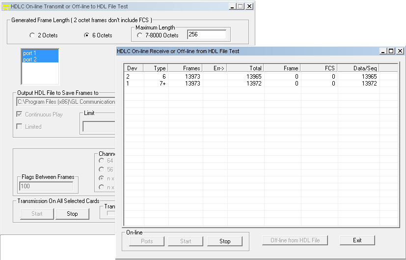
The HDLC Automated Test System consists of two applications: Transmitter application and Receiver application. Each application has real-time and off-line features. The Transmitter application generates HDLC test frames using special algorithms, transmits them over Datacom ports or records them to an HDL file for subsequent use with other applications.
The Receiver application can receive frames in real-time over Datacom or can verify an off-line HDL file for correct frame order and data integrity.
 Back to List of T3E3 Basic and Optional Applications Main Page