T1/E1 ATM BERT
ATM BERT application is included with T1 E1 Basic Software
Overview
GL's T1/E1 ATM Bit Error Rate Test (BERT) application permits BER testing across an ATM channel operating over PDH circuits.
A typical ATM BERT application is the verification of end-to-end integrity in an ATM virtual connection as shown below:
Screen Shot of Main GUI
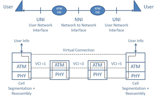
A typical ATM circuit
The application transmits a BERT pattern using the simplest ATM Adaptation Layer, i.e. AAL0. The BERT pattern is inserted in its entirety into the 48 byte payload of the cell. This is shown graphically below. Cells are either "BERT payload" or "idle" cells. Note that "cell headers" and payload can overlap the framing position.
In contrast to traditional BERT, ATM BERT is done at the ATM layer and can be performed all of the way across the virtual circuit to the far-end customer-premise site. Often, user traffic may be routed through several CO sites before reaching the first ATM edge switch. Each of these additional routes adds to the potential for errors. Traditional BERTs may only verify the local loop to the first CO and neglect to verify the connections between the intermediate COs. Thus ATM BERT allows for end-to-end verification of the circuit's reliability.
The application allows traffic generation and verification, bit error insertion, looping back incoming traffic, and configuring ATM header fields such as virtual path and circuit identifier values, GFC, PT, and CLP for UNI & NNI interfaces.
The application is capable of testing Pseudo Random Bit Sequence (PRBS) patterns, fixed patterns like all ones, all zeroes, alternate ones & zeroes, 1:1, 1:7, and user-defined bit patterns. In addition, single bit error insertion rate, error insertion from 10-2 to 10-9, invert, and scrambling options are provided for payload.
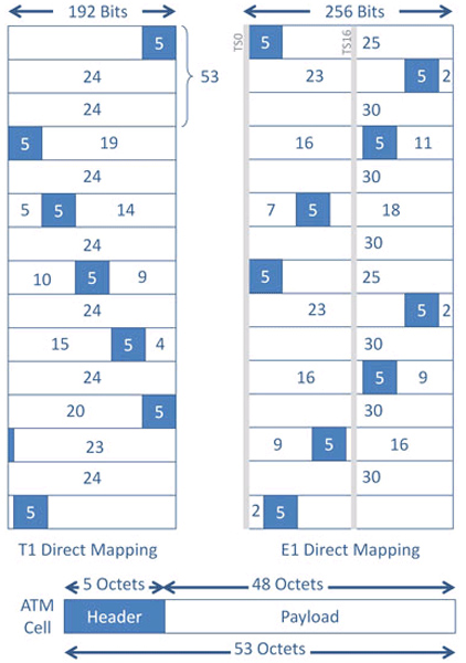
T1 and E1 ATM Direct Mapping
Transmit and Receive ATM BERT Block Diagram
Typical transmit and receive ATM BERT block diagram is as depicted below -
Transmit ATM BERT Block Diagram
Receive ATM BERT Block Diagram
GL has various tools for analyzing and testing ATM. For example, ATM Analyzer, Inverse Multiplexing over ATM (IMA) Analyzer, T3 E3 ATM Analyzer, OC-3 STM-1 OC-12 STM-4 ATM Analyzer and many others
Note: Currently this application is not available on Octal/Quad T1 /E1 Analyzers.
Main Features
- Capable of generating/receiving ATM traffic
- Support user-defined ATM header configuration for GFC, VPI, VCI, PT, CLP
- User-defined traffic rate to the accuracy of 1% of total bandwidth
- Supports different QRSS, PRBS patterns 29-1, 211-1, 215-1, 220-1, 223-1, All one's, All zero's, alternate 1's and 0's, 1:1, 1:7, & User-defined patterns. User defined patterns length can be 3 to 32 bits in length
- Supports inverting, and scrambling payload data. Scrambling is according to ITU-T G.804
- Supports single bit error insertion, and error rate insertion
- Provides ATM QoS measurement (Bit error count/ Rate/Seconds, Sync Loss, No Rx data,... )
- Provides ATM Statistics (total cell count, rejected / pass / idle cell counts, cell rate, and HEC error count)
- Error and Alarm LEDs for easy analysis
- Supports testing on multiple cards simultaneously with consolidated result view
- Tx and Rx settings for multiple cards can be independently controlled or coupled
- Capability to save and load the configuration settings
ATM Header Configuration
T1/E1 ATM BERT application allows configuring the ATM header fields such as GFC (Generic Flow Control), VPI (Virtual Path Identifier), VCI (Virtual Channel Identifier), PT (Payload Type), and CLP (Cell Loss Priority). ATM header GFC (Generic Flow Control) field is enabled only for UNI interface.
On the Rx side, user selectable Filters for ATM header are provided, which are used to accept/reject incoming ATM cells.
TX Configuration Window
RX Configuration Window
BER Pattern Configuration
Payload option in the Tx and Rx configuration allows user to select specific Bit Error Rate test pattern for transmission. T1/E1 ATM BERT supports various BERT patterns; QRSS, PRBS patterns such as 29-1, 211-1, 215-1, 220-1, 223-1, fixed patterns like all ones, all zeros, alternate 1s and 0s, 1:1, 1:7, & and user-defined patterns. User defined patterns length can be 3 to 32 bits in length. Other options such as invert & non-invert selections, and scrambling options (according to ITU-T G.804) are provided. On the receive side, the configured BERT pattern is used to match incoming traffic and to declare "SYNC" and measure various BERT statistics.
BER Pattern Configuration
Traffic Rate
The Traffic Rate to be generated can be configured in 2 ways:
- Percent of total bandwidth with range starting from 1% to 100%
- Cell Ratio, where users can set the ratio of ATM traffic cells to idle cells
Traffic Rate
Bit Error Insertion
ATM BERT allows users to insert single bit error or constant error rate from 10-2 to 10-9 into the outgoing (TX) BERT stream.
Bit Error Insertion
BERT Results & Tx/Rx Cell Statistics
The Result screen displays both BERT Status with LEDs and BERT Statistics. LEDs give users a quick way of viewing the test status. The three Status LEDs reflect current as well as history status. These LEDs indicate the Traffic status (whether traffic is being received or not), Pat Sync status (In Sync or Sync Loss) and Bit Error Status (whether Bit Errors are present).
Bert Results provides a more detailed view of the test results. Various results like the Bit Error Rate (the average bit error rate since the start of the test calculated as a ratio of the total bit errors occurred to the total bits received), the number of times/number of seconds Bit Error, Sync Loss, No Rx Data events occurred, Number/Seconds of Error Free events etc. are displayed.
The application also provides ATM cell statistics such as total cell count, rejected / pass / idle cell counts, cell rate, and HEC error count.
BERT Results
BERT Statistics
ATM Background
Asynchronous Transfer Mode, or ATM is a form of transmission and switching that is commonly used on DSL (Digital Subscriber Lines), fiber optic lines, and 3G mobile infrastructures. Transmission systems could be any digital facility including: T1, E1, DSL, T3, E3, OC-3, STM-1, OC-12, STM-4, and other higher rates.
ATM is based on segmenting all information regardless of type (voice, data, picture, or video) into "cells" of length 48 bytes plus 5 overhead bytes (53 total). At the receiving end, the reassembly of these cells puts the information back to its original state. To handle all information types many higher layer protocols have been developed called ATM Adaptation Layers, or AALs.
ATM's basic advantages include lower latency (compared to IP), efficient and fast switching speeds, little or no congestion, and versatile traffic type handling. Its major disadvantages are the large overhead consumed for each cell and the finite time required to pack and unpack a 53 byte cell (versus a single byte in TDM).
Of course, the competing and proliferating technology is IP (Internet Protocol). IP will likely dominate in the future as it invades all forms of transmission and switching. But for now, a significant amount of network transmission and switching remains ATM. One major ATM application is the reuse of copper subscriber lines for internet data (the world is replete with copper subscriber lines!). Another is in the mobile broadband system infrastructure called 3G - think "smartphones". All this means that most traffic gets converted to ATM at some time during its traversal.
Resources
Note: PCs which include GL hardware/software require Intel or AMD processors for compliance.
Please Note1: The XX in the Item No. refers to the hardware platform, listed at the bottom of the Buyer's Guide, which the software will be running on. Therefore, XX can either be ETA or EEA (Octal/Quad Boards), PTA or PEA (tProbe Units), depending upon the hardware.
| Brochure |
| T1E1 ATM BERT Brochure |
| Presentations |
| T1E1 ATM BERT Presentation |
* Specifications and features subject to change without notice.