GL Announces Echo Mitigation Software
18th, May 2018
Welcome to another May 2018 issue of GL's Newsletter providing information and insight into our enhanced Echo Mitigation System (EMS) Software that can be deployed on the backhaul systems to eliminate the varying delay/echo resulting from different backhaul technologies used to transport audio through the system.
Overview
Variations in delay can potentially cause gaps in the speech. The greater the time discrepancy between audio signals, the more difficult to understand the message.
Echo Mitigation System (EMS) by GL Communications can be deployed on the backhaul system to eliminate the delay/echo.
EMS solution allows for the measurement of delay from each site of a group of radio sites as well as the application of offsetting delays to mitigate the echo impairment.
During the echo mitigation process, a user configurable delay is applied to each DS-0 in each T1 for east and west directions (48 DS0s / per duplex T1) and each DS-0 may be configured with its own delay parameter. This helps to synchronize inbound and outbound audio delivered to end users (or dispatch operators). For example, in an Octal T1 system, all 192 DS0s / all T1s (8 T1s) can be applied user configurable delays.
EMS Solution Capabilities
When a carrier provided DS0 circuit is placed into loopback at a remote site, the system will be able to initiate a circuit delay test on that DS0. EMS Software performs round-trip delay measurements. One-Way delay measurement available using companion equipment. This measurement will facilitate the configuration of the circuit delays required to bring the audio signals into sync. The EMS software contains a configuration utility through which users specify these delay values. EMS functionality can be enabled or disabled at both DS1 and DS0 levels.
The system will be able to inject circuit delays without degrading or disrupting communications using the standard timings of 3.0 ms on a D4 format circuit, and 6.0 ms on ESF format. Minimum delay steps 3 milliseconds in ESF mode. Delay is implemented via a delay buffer scheme with the ability to add circuit delays independently in the transmitting and receiving paths of a DS0.
The user interface will also provide the ability to assign DS0 and DS1 circuits names for extended information to identify the circuits.
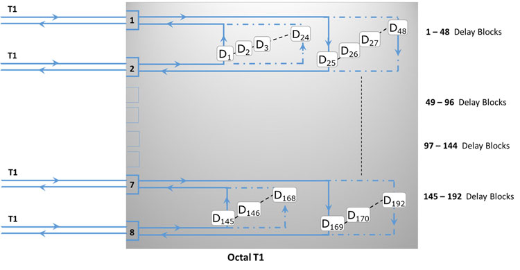
Given in the table below is GL’s EMS solution on Octal T1 Rackmount System. This system allows all 192 DS0s (all 8 T1s) to be individually assigned their own delay parameters.
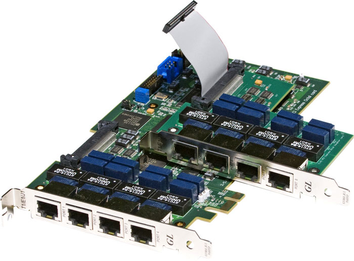
Octal T1 Card (EMS)
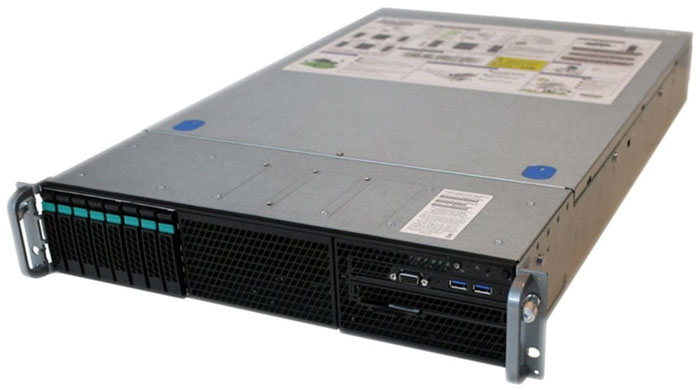
2U Rack Intel® Server System
The below is the screenshot of EMS application within Octal T1 Rackmount System:
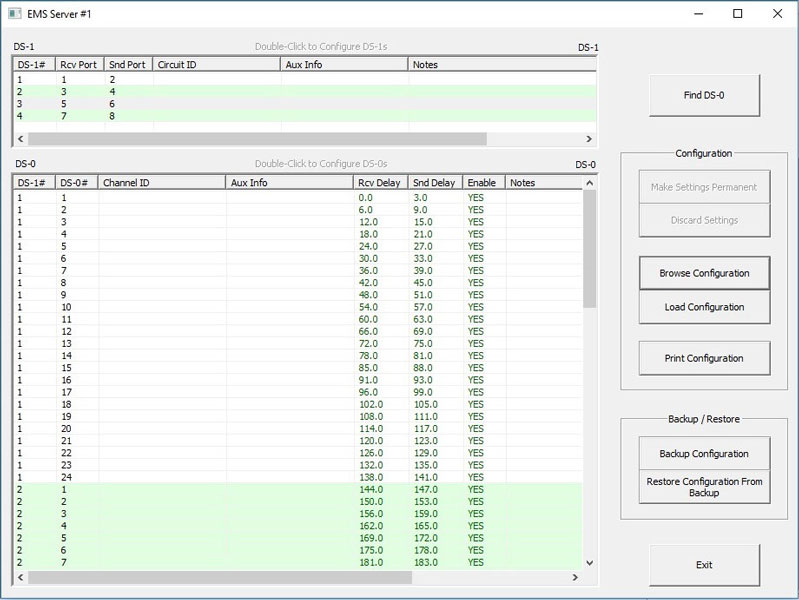
EMS Delay Configuration
Related Applications
Delay / Attenuate Simulation
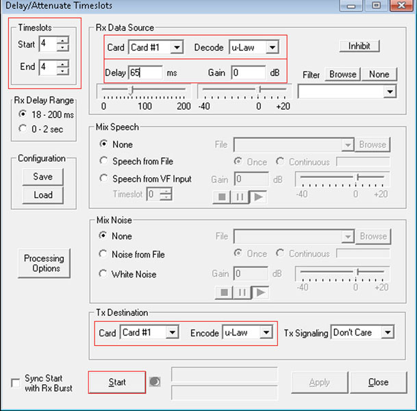
- Allows to apply delay, attenuation, and/or filtering to a received signal on any number of timeslots
- An "input-process-output" application -
- data is retrieved from the Rx Data Source;
- processed by delaying, attenuating, and/or filtering it;
- retransmitting the processed block on the Tx Destination.
- Mix in additional signals from a number of sources, including
- speech and/or Noise signals from files
- speech signals inserted via VF input
- gaussian noise signals generated internally
For more details, visit Delay / Attenuate Timeslots web page.
Delay/Attenuate - Single Channel
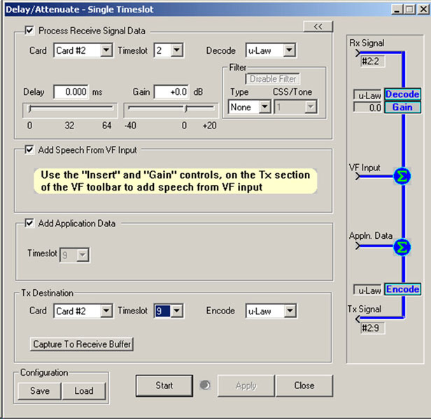
- Facilitates Low Delay Echo Path Modeling
- Apply delay, attenuation (gain), and/or filtering to a received signal on a single timeslot
- Mix-in additional signals from other sources, Speech signals inserted via VF input and Gaussian noise signals or Tone generated internally
For more details, visit Delay/Attenuate Single Timeslot web page.
Measure Loop Delay & Echo Return Loss
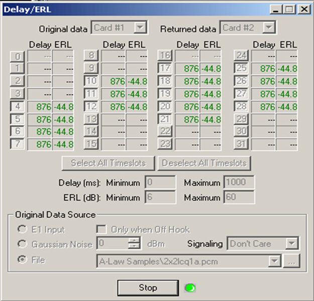
- Provides the capability to measure and display Loop Delay and Echo Return Loss (ERL) on one or more timeslots
- Supports two basic modes of operations –
- Non-Intrusive: Two GL boards are used, one of which monitors the original signal while the other monitors the returned or looped-back signal
- Intrusive: One or two GL boards are used. A signal is injected into one or more timeslots and the returned signal is monitored
- Multiple instances of this application may be opened simultaneously, allowing measurements to be taken on multiple timeslot ranges and measurement strategies
For more details, visit ERL Loop Delay web page.
Precision Delay Measurement
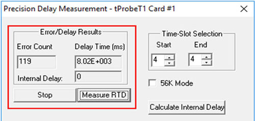
- Measures the Round-Trip Delay of a system
- Measurement is precise and accurate to the microsecond level
- A delay up to 8 seconds can be measured. The internal delay of the card is subtracted from the round-trip delay
For more details, visit Precision Delay Measurement web page.
 Back to Newsletter Index Page