FDL Software for Emulation and Analysis
Overview
GL's Facility Data Link (FDL) software consisting of several powerful modules that have the capability to transmit, receive, and decode FDL data in many ways as described below:
- FDL Protocol Analyzer: Analyzes the incoming FDL data stream according to different FDL standards and specifications like T1.403, T1.408, G.963, I.431, and G.704. Whether the FDL data is HDLC frames or "bit oriented messages", the data is decoded, stored and presented for visual inspection. FDL data can be stored for later analysis as well
- FDL Playback GUI application: This software can playback raw data from files as well as files containing HDLC frames into the T1 FDL. The user may transmit valid HDLC frames (properly formed HDLC frame file required), or the user may transmit raw data from a file of raw (hex) bytes (codeword strings, etc.). When transmitting HDLC frames, the number of flags between frames may be selected. File playback for HDLC or raw bytes may be set to continuous, to end-of-file, or for a specified number of bytes
- FDL View & Save GUI application: Displays captured FDL bits, CRC bits, and framing bits as well as logging for future analysis. The view window refreshes automatically, and the user has the option of saving to a file the complete capture of all bytes received since the capture was started
- FDL VB Client for Windows Client Server: The Client Server Scripted Control Software has commands to record FDL data, playback FDL files, and playback user specified FDL data. A user friendly VB Client has been written to interface with the Server to emulate various FDL functions. Options for Tx and Rx different Performance Report Messages (PRM/SPRM/NPRM) are provided. The VB client also can playback/receive a list of code words and it also can transmit/receive user defined Rawdata /ASCII words
FDL Protocol Analyzer
The FDLA module performs FDL decode and analysis on T1 channels in both real time and off-line using saved files with high level data link (HDLC) frames and bit-patterned extended super frame (ESF) data link messages. The FDL requires ESF mode.
The real-time mode of operation is used to capture stream of HDLC frames on the selected cards and also embedded bit-patterned ESF data link messages. Captured information can be saved to disk for later off-line analysis.
Both real-time and off-line analysis present information in two layers:
- Raw HDLC Frame data as a hexadecimal and ASCII octet dump
- FDL message information
HDLC frames are parsed according to Q.921, FDL messages are decoded based on the AT&T TR54016, ANSI T1.403, T1.408, I.431, G.963 and G.704.
Multiple instances of FDLA can run simultaneously capturing data from several T1 lines. Each instance can capture data from up to four T1 lines.
The frame information is displayed in two panes: summary view and detailed view. The detailed view pane displays the detailed information that includes all layers and can be exported to an ASCII file for the further off-line analysis.
Captured Frames can later be used for traffic simulation using the FDL transmit application.
Summary & Detail View
FDLA user interface has two panes: the summary view at the top and the detail view at the bottom. The splitter separating the summary and the detail views allows dividing screen according to user preferences. The summary view columns can be resized and reordered using drag operation.
Summary View
Columns of the summary view can be resized and/or reordered using drag and drop mouse operation. The screenshot below shows the "Time" column was resized, "Address", "From" and "Type" columns were moved.
The default summary view displays the following information in the tabular format left to right:
- Card number (one relative)
- Frame (message) number (zero relative)
- Relative time from the beginning of the capturing as HHH:MM:SS.xxxxxx
- Frame length including 16 bit FCS for HDLC frames
- Error status
- LAPD/LAPB address
- Control
- Site (NI - network interface, CI - customer installation)
- Message Type
- Information (beginning of message data in hex format)
The left mouse button click highlights a frame and displays it in the detail view. The current record, the upper frame in the summary view, remains unchanged as seen in the screenshot below.
The left mouse button double click changes both the current frame and the detail view as seen in the screen shot below.
Detail View
The detail view displays Frame information in the following sequence:
- Frame Summary Information
- LAPB or LAPD address and control
- Message Details///
- Hexadecimal dump of all Frame octets
Real-time and Off-line Analysis
Real-time Analysis
The real-time analysis is used to capture data on one or multiple T1 lines. The captured data is always stored in a temporary file. Before capturing is started, the capturing options and timeslots must be specified. These settings are saved in the Windows registry and can be reused between FDLA sessions.
Off-line Analysis
The off-line mode of operation can be used to analyze a trace saved in a file during real-time analysis.
Interface and Operation Features (Detailed)
The main menu and the tool bar are used to select an operation to perform. The status fields at the bottom of the window display miscellaneous FDLA status information. Most of the operations can be performed either using the main menu or the correspondent tool button. The following lists of links describe the user interface items and the correspondent operations in more detail. Both screenshots and descriptions are provided.
- Setting Capturing Options
- Specifying Card Selection for Real-time Analysis
- Starting Real-time Analysis
- Suspending Real-time Capturing
- Closing the Current Real-time or Off-line Trace
- Saving Current Trace with a New File Name
- Opening a Trace for Off-line Analysis
- Automatic Screen Refresh During Real-Time Analysis
- FDL Encoding Standard Option
- Exporting Trace to an ASCII File
- Repositioning the Summary View
FDL View and Save Data
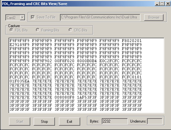
The View And Save Data module within the FDL optional software package allows the user to view, in real time, the raw hex bytes being received from the FDL bit stream, the Framing bit stream, or the CRC bit stream. The view window refreshes automatically, and the user has the option of saving to a file the complete capture of all bytes received since the capture was started.
FDL Playback File
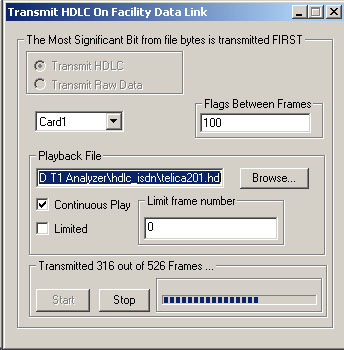
The Playback File module within the FDL optional software package allows the user to transmit data directly into the FDL bitstream. The user may transmit valid HDLC frames (properly formed HDLC frame file required), or the user may transmit raw data from a file of raw (hex) bytes (codeword strings, etc.). When transmitting HDLC frames, the number of flags between frames may be selected. File playback for HDLC or raw bytes may be set to continuous, to end-of-file, or for a specified number of bytes.
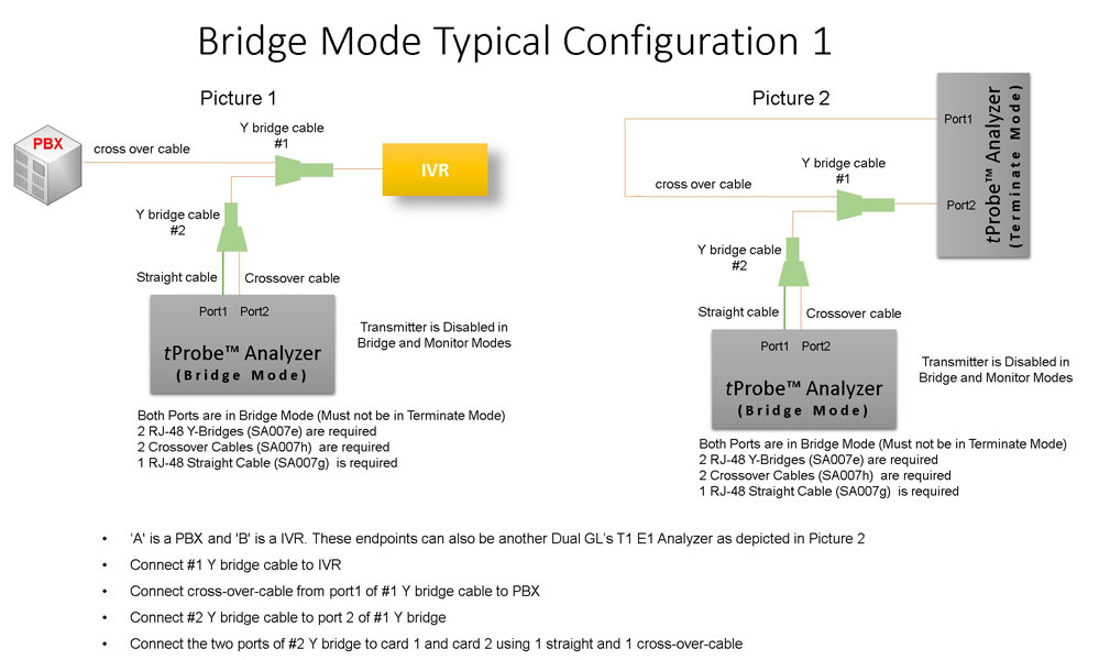
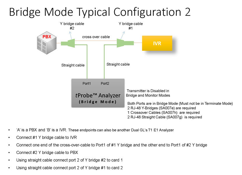
Bridge and Monitor Connections
- Monitor from a DSX-Patch Panel
- Bridge Mode Connections for Monitoring T1/E1 Signals for RJ-45
- Bridge Mode Connections Alternative Method
- RJ-45 Connections
Resources
Note: PCs which include GL hardware/software require Intel or AMD processors for compliance.
Please Note: The XX in the Item No. refers to the hardware platform, listed at the bottom of the Buyer's Guide, which the software will be running on. Therefore, XX can either be ETA or EEA (Octal/Quad Boards), PTA or PEA (tProbe Units), XUT or XUE (Dual PCIe Express) depending upon the hardware.
| Item No. | Item Description |
|---|---|
| XX021 | Facility Data Link (FDL) Analyzer |
| XX660 | WCS with FDL option and VB Client to control FDL |
| Related Software | |
| XX090 | HDLC Capture and Playback Software (T1 or E1) |
| XX100 | ISDN Analysis Software (T1 or E1) |
| XX120 | Real-Time SS7 Analyzer Software (T1 or E1) |
| XX130 | Real-Time Frame Relay Protocol Analyzer (T1 or E1) |
| Related Hardware | |
| FTE001 ETE001 |
QuadXpress T1E1 Main Board (Quad Port– requires additional licenses) OctalXpress T1E1 Main Board plus Daughter Board (Octal Port– requires additional licenses) |
| PTE001 | tProbe™ Dual T1 E1 Laptop Analyzer with Basic Analyzer Software |
| XTE001 |
Dual T1 E1 Express (PCIe) Boards (requires additional licenses) |
| Brochure/ Presentation |
| FDL Protocol Analysis Emulation Brochure |
| Protocol Analysis and Emulation - Presentation |
 Back to Protocol Analysis Index Page