IP WAN Emulator (IPNetSim™ & IPLinkSim™)
IP WAN Link Emulators test the performance of real networks by emulating impairments such as packet loss, packet corruption, packet duplication and packet reordering.
Request a Demo / Quote Brochure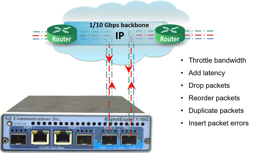
Overview
GL’s IP WAN Link Emulators are designed to evaluate network performance by deliberately introducing impairments such as packet loss, corruption, duplication, and reordering. These impairments can be safely and reversibly applied, allowing equipment manufacturers, network engineers, application developers, and service providers to analyze how networks and applications behave under adverse conditions.
The two main emulator applications, IPNetSim™ and IPLinkSim™ (IPN507), are optional modules within the PacketExpert™ (PXN100) platforms.
IPNetSim™ simulates a bidirectional WAN IP link with either a 10 Gbps or a 10/100/1000 Mbps full-duplex line. It can classify incoming traffic into multiple user-defined streams—up to 16 streams for 1 Gbps and up to 4 streams for 10 Gbps links. Each stream can be independently modified to introduce various network impairments.
IPLinkSim™ emulates a single-stream WAN IP link at 10 Gbps or 10/100/1000 Mbps full duplex, applying impairments uniformly across all traffic as one stream.
Both emulators are also available as part of the mTOP™ (MT001) rackmount appliance, which stacks PacketExpert™ 10GX (PXN100) USB units to provide a high-density Gigabit Ethernet testing solution. This appliance includes all features of the portable units along with integrated PC hardware running Windows® OS and supports remote access via Ethernet Remote Desktop.
To use, simply connect the PacketExpert™ IPNetSim™ or IPLinkSim™ device in series with existing optical or electrical network links. Users can then introduce impairments such as bandwidth throttling, latency, jitter, packet loss, reordering, duplication, corruption, and error insertion to test applications before live deployment.
Both IPNetSim™ and IPLinkSim™ offer Command line Interface (CLI) access for remote control via Python, C# clients, or MAPS™ CLI client/server architecture, enabling automation and integration into testing workflows.


What makes the GL traffic impairment solution stand out in the market
Our solution offers unmatched flexibility, precision, and ease of use for network testing and simulation.
- Targeted Traffic Impairment: Users can selectively impair specific traffic streams based on IP addresses, ports, and other criteria — or apply impairments globally across all traffic. This allows for highly controlled and realistic test scenarios
- Comprehensive Impairment Options: We support six types of impairments — bandwidth throttling, added latency, packet loss, duplication, reordering, and bit error insertion — covering all critical real-world network conditions
- Live Insights: Real-time graphs and statistics provide instant feedback, helping users visualize the effects of impairments and make informed decisions quickly
- Built-in Scheduler: Our powerful Scheduler feature enables users to automate impairment profiles over different time periods without stopping or restarting tests. It ensures continuous testing with seamless transitions, saving time and improving test coverage
Key Features
Multi-Stream & Single-Stream Modes
- IPNetSim™: Emulates up to 16 bidirectional WAN links (1 Gbps ports) or 4 streams (10 Gbps)
- IPLinkSim™: Single bidirectional WAN link emulation per unit
- mTOP™: Rack-mountable, scalable solution supporting high-density, multi-device configurations
Flexible WAN Emulation
- Emulates WAN conditions independently in each direction
- Functions as a transparent Ethernet bridge for seamless integration
Advanced Stream Definition
- Classify traffic into streams using header fields: MAC, VLAN, MPLS, IPv4, UDP, etc.
- Supports both raw (bit-level) and packet-mode configurations
- Stream width: Up to 120 bytes; offset range: 0–2047 bytes for full header/payload control
- Independent impairments per stream; per-stream statistics and real-time graphs
Comprehensive WAN Impairments
- Bandwidth Control: 1 Kbps to 10 Gbps
- Latency: 0–1.5 sec (1G) / 0–0.5 sec (10G); single, uniform, random delay modes
- Packet Loss: 0–50%
- Reordering: 0–100%, up to 2 sec delay
- Duplication: 0–50%
- Bit Error Insertion: 10-1 to 10-9 rates
Automation & Control
- Scheduler supports CSV-based automation for bandwidth, latency, and loss
- Periodic and random impairment patterns supported
- Ethernet Pause frame support for link throttling
- CLI for automation and remote testing
Additional Capabilities
- Max frame size: 2048 bytes
- Real-time per-stream throughput monitoring
Frequently Asked Questions
- Can PacketExpert™ 10GX impair real application traffic such as software downloads?
- Yes. When IPLinkSim™ or IPNetSim™ is loaded, PacketExpert™ 10GX operates as a transparent Ethernet bridge. It passes real traffic unchanged when emulation is OFF and applies bandwidth, latency, jitter, and packet loss impairments when emulation is ON.
- Does PacketExpert™ 10GX behave like a LAN cable when impairments are disabled?
- Yes. With emulation disabled, the system functions as a simple bi-directional LAN cable, transparently forwarding traffic between connected devices.
- Why do impairment specifications vary across documents?
- Impairment limits depend on the application and port speed. There are four supported combinations:
- IPLinkSim™ 1G
- IPLinkSim™ 10G
- IPNetSim™ 1G
- IPNetSim™ 10G
- What bandwidth ranges are supported?
- IPLinkSim™ 1G / IPNetSim™ 1G: 10 Kbps to 1 Gbps (0.5 Kbps steps)
- IPLinkSim™ 10G / IPNetSim™ 10G: 10 Kbps to 10 Gbps (0.5 Kbps steps)
- What latency and jitter models are supported?
-
- Constant (Single Delay)
- Uniform Distribution Delay
- Random Exponential Distribution Delay
- What packet loss and corruption options are available?
-
- Packet Loss: Periodic and Random (Random loss supported in IPLinkSim™)
- Packet Corruption: Logic Error Insertion and FCS Error Insertion
- Additional Effects: Packet Reordering and Packet Duplication
- Can impairment behavior be captured as graphs for test evidence?
- Throughput-versus-time graphs are available. However, individual impairment parameters are not logged or graphed. Validation can be performed using PacketExpert™ traffic generation and analysis tools if required.
- What are IPNetSim™ and IPLinkSim™ used for?
- IPNetSim™ and IPLinkSim™ are WAN link emulators used to simulate real-world network impairments such as latency, jitter, packet loss, bandwidth throttling, and errors to test and evaluate network and application performance under controlled conditions.
- How does IPNetSim™ differ from IPLinkSim™?
- IPNetSim™ supports multi-stream emulation with independent impairments on up to 16 streams (1 Gbps) or 4 streams (10 Gbps), allowing simultaneous emulation of multiple WAN scenarios. IPLinkSim™ operates in single-stream mode, applying impairments to all traffic as one stream and can generate background traffic for congestion emulation.
- How do these emulators safely introduce network impairments?
- They operate as transparent inline Ethernet bridges between two network points, applying impairments only to the test traffic passing through. Impairments are user-configurable, reversible, and can be started or stopped at any time, ensuring no permanent disruption to the live network.
- What types of network impairments can be emulated?
- Both emulators can emulate bandwidth throttling, latency, jitter, packet loss, packet duplication, packet reordering, packet corruption, and error insertion with configurable parameters and patterns (periodic or random).
- Can the emulators be controlled remotely or automated?
- Yes, both IPNetSim™ and IPLinkSim™ support command line interfaces (CLI) for remote control and automation using scripts or third-party applications, enabling precise and repeatable test scenarios.
- What platforms support IPNetSim™ and IPLinkSim™?
- They are available as applications on GL’s PacketExpert™ (PXN100) portable units and the rackmountable mTOP™ appliance, supporting 1 Gbps and 10 Gbps full duplex Ethernet links.
- Is the delay solution FPGA based, or RAM based?
- Yes, our solution is FPGA based. Not Operating system based, it can handle traffic at wirespeed without loss. No OS based or software-based latency.
- Does the solution support both multimode (850 nm) and single-mode (1310 nm) fiber with an LC connector?
- Yes, our solution supports a multitude of Ethernet standards including 10/100/1000 Mbps Ethernet, 2.5 Gbps, 10 Gbps. We support copper and fiber optics (single-mode and multi-mode).
- What are the key advantages of this solution when compared to similar products on the market?
-
- Users can define which 'streams' of traffic they wish to impair (based on IP addresses, UDP/TCP ports, etc.). Each stream can be impaired independently of other streams. Users can also impair all traffic equally if they wish
- Comprehensive Impairment Options: Six different types of impairments are possible
- Bandwidth reduction
- Added latency
- Packet loss
- Packet duplication
- Packet re-ordering
- bit error insertion
- Real-Time Monitoring: Real-time graphs and statistics depicting the impaired traffic
Software Specification
| Multi-streams WAN Emulation - IPNetSim™ | Single-stream WAN Emulation - IPLinkSim™ |
|---|---|
Stream Definition
Parameters
|
-NA- |
WAN Emulation Parameters
|
WAN Emulation Parameters
|
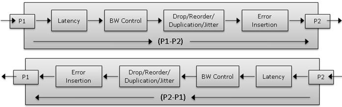
Working Principle
PacketExpert™ is connected to the 2 end points of a WAN link. It can be configured to act either as a transparent bidirectional Ethernet link or a simple Ethernet bridge between 2 end points. The links are emulated between Port 1 (P1) and Port 2 (P2). The bandwidth can be controlled to simulate various WAN link speeds (RS232/DSL/Modem/T1/E1/T3/E3 etc.).
P1 -> P2 is one link and in the reverse direction, i.e., P2 -> P1 forms the other link. By default, P1 and P2 work in pass-through mode, and pass all frames across to the other port. Frames arriving at P1 are carried over to P2 and frames arriving at P2 are carried over to P1.
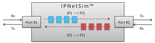
Transparent Bidirectional Link (P1-P2)/(P2-P1)
In multi-stream mode (IPNetSim™), user can define multiple streams in each direction (based on various header fields) to classify traffic into multiple streams. For each stream, a different set of WAN Emulation parameters can be applied, a single IPNetSim™ can emulate different WAN scenarios like Head Office to Data Center, Head Office to Branch Office etc.
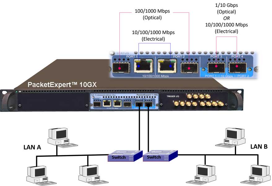
IPNetSim™ on PXN100 (Multi-Stream/Single Stream WAN Emulator) connecting 2 network end points
WAN Emulation includes various real-world impairments such as Bandwidth, Latency, Packet-Loss, Error Insertion, Reordering, and Duplication, to check the performance of end equipment to real world impairments. These settings can be applied for the selected 16 unique streams on 1Gbps link and 4 unique streams on 10Gbps link independently in each direction.
Traffic (bidirectional streams) can be processed at wirespeed (1Gbps or 10Gbps). Bidirectional streams can be configured as a symmetrical (identical WAN impairments in both directions) or asymmetrical (different WAN impairments in each direction). WAN impairments can be configured independently for each stream. When WAN Emulation is started by the user, the impairments are introduced into the traffic as shown below.
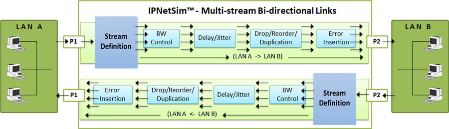
Impairing Multi-streams over P1->P2 and P2->P1 Link
In single stream mode (IPLinkSim™), all the incoming traffic is streamed as a single link, which can be impaired with various link conditions such as Bandwidth Control, Latency, Packet Loss, Packet Reordering, Packet Duplication, Error Insertion emulating real-world scenarios.
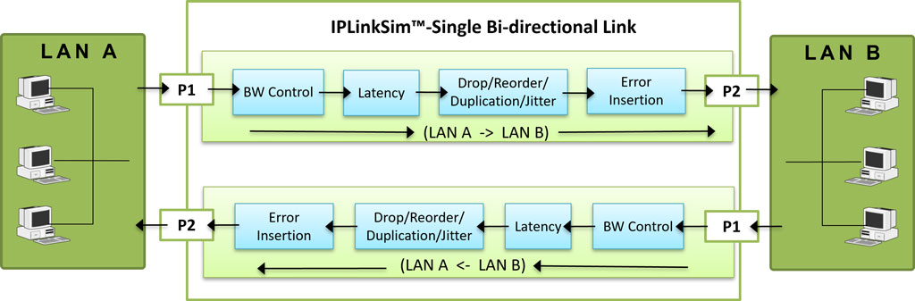
Impairing Single stream over P1->P2 and P2->P1 Link
Stream Definition
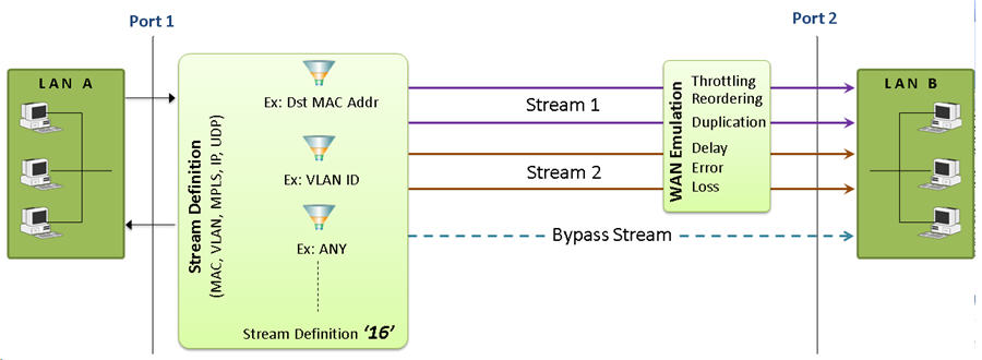
As depicted in the figure, IPNetSim™ includes a powerful “Stream Definition” feature that permits user to configure MAC, IP, VLAN, MPLS, UDP header fields to classify the traffic flows.
There are two actions for the stream definitions:
- Stream: Packets matching the stream definition are sent as specified stream.
- Bypass: Packets not matching the stream definitions are forwarded without emulation.
For each stream, user can define the stream parameters separately for each direction (P1 ->P2 and P1 <- P2). Streams can be defined in two modes – Packet Mode or Raw Mode.
In Raw mode, user can select a 120 byte window anywhere within the frame (starting from MAC Destination Address field till the end of Payload) to compare and identify the stream using raw hex data (120 bytes) and an offset. User can also define a corresponding 120 byte Hex mask, so that each bit can be set to ‘Compare’ or ‘don’t care’ conditions. For each stream definition, offset can be set to any byte within the packet (from 0 to 2047) which gives flexibility to define any fields within any protocol headers, and even the payload
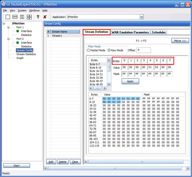
Stream Definitions in Raw Mode
(16 streams on 1G ports)
In Packet mode, each field can be compared against either a fixed value, a range of values or ANY value. Various packet field values can be edited directly as per the layer stack (L2/L3/L4) selected. Streams can be defined based on various fields like Source/Destination MAC Address, VLAN Id, MPLS Label, Source/Destination (IPv4 and IPv6) Addresses, Source/Destination UDP ports etc.
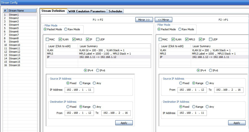
Stream Definitions in Packet Mode
(16 streams on 1G ports)
Stream Statistics
This option provides real-time transmission statistics for each stream (16 streams on 1 Gbps ports and 4 streams on 10 Gbps ports) over the emulated bi-directional link (P1-P2) / (P2-P1). The statistics include Tx and Rx frame statistics for each port, Dropped Packets (due to Bandwidth Control), No. of Packets with Errors, Dropped Packets (due to Packet Loss), Duplicated Packets, and Reordered Packets for varying durations.
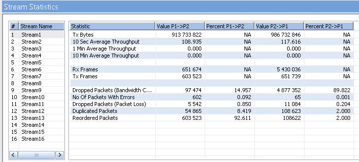
IPNetSim Stream Statistics
(16 Streams on 1G ports)
IPNetSim Stream Statistics
(4 Streams on 10G ports)
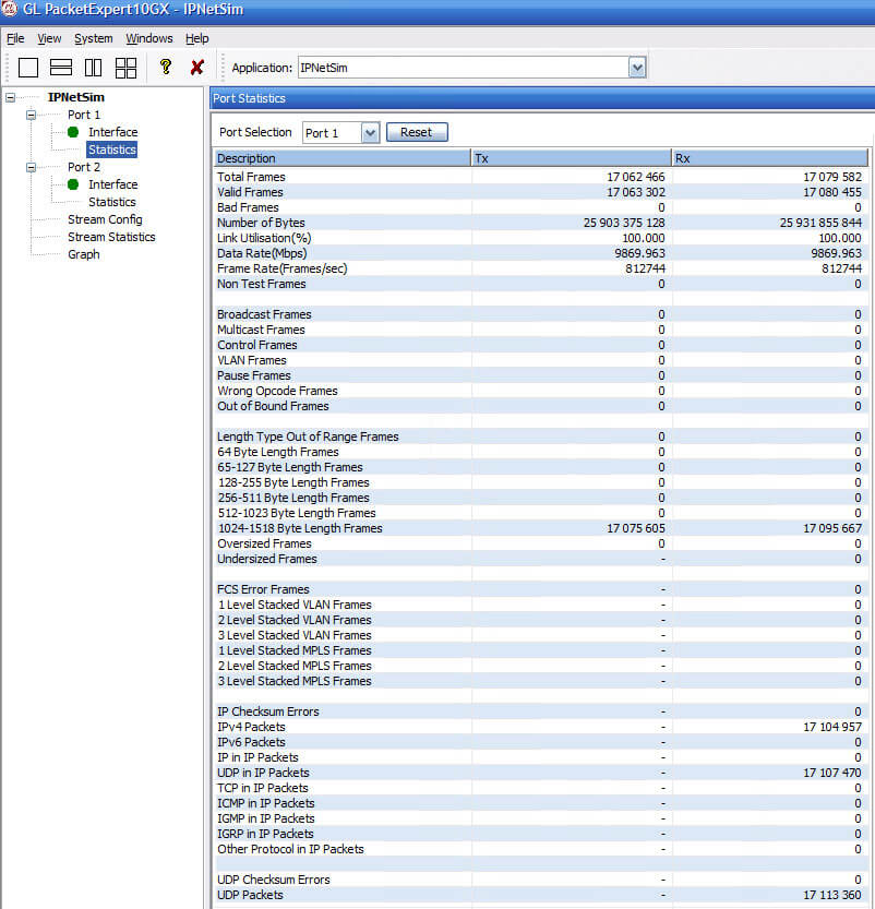
IPNetSim™ Port Statistics
Stream Throughput Graph
The real-time Throughput of each stream, plotted as rate against time, is displayed in the form of a line graph. All the streams (16 streams on 1G ports and 4 streams on 10G ports) throughput can be viewed together, or user can select or deselect each stream to view separately. Graphing is supported from 5 seconds up to 7 days.
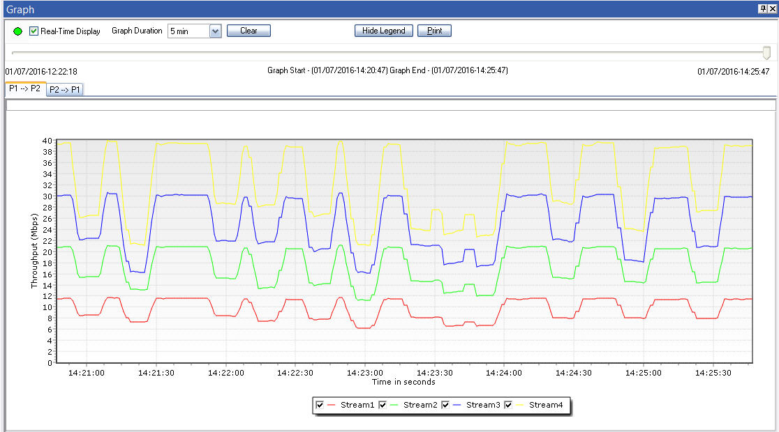
Screen Shot of IPNetSim streams Graph
(4 streams on 10G ports)
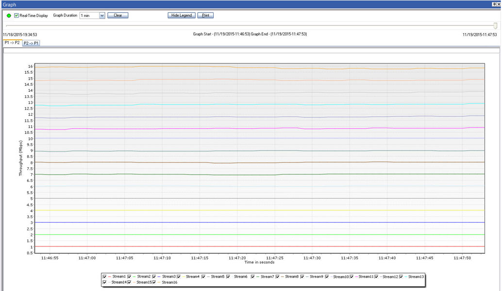
Screen Shot of IPNetSim streams Graph
(16 streams on 1G ports)
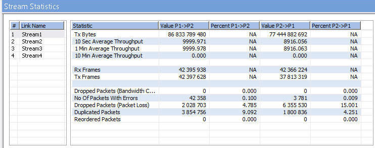
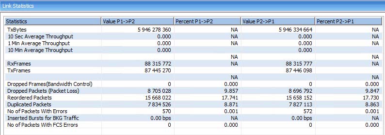
Link Statistics
This option provides real-time transmission statistics of the traffic over the emulated link (P2-P3)/(P3-P2) in each direction. The statistics parameters include Dropped Packets (Bandwidth Control), No. of Packets with Errors, Dropped Packets (Packet Loss), Duplicated Packets, Reordered Packets, and Background Traffic Bandwidth, for varying durations.
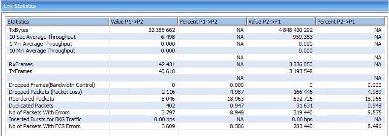
1G Link Statistics
10G Link Statistics
Link Throughput Graph
The graph displays the real-time Throughput of the link, plotted as rate against time, in the form of a line graph. The Graph can be viewed for a single link or both the links together.
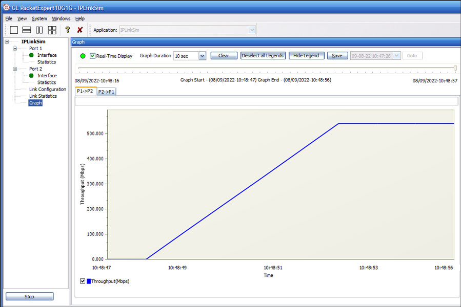
1G Link Graph
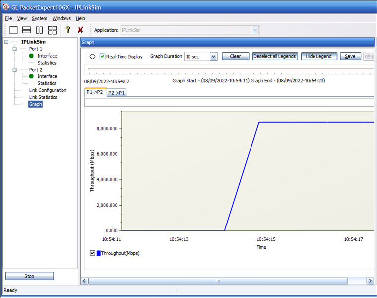
10G Link Graph
WAN Link Impairments
GL's IPNetSim™ WAN emulator is capable of emulating a WAN link, and introducing typical WAN impairments like Bandwidth Throttling, Latency, Jitter, Packet Loss, Packet Reordering, Packet Duplication, Packet Corruption, , Error Insertion, etc.
IPNetSim™ supports user defined streams to classify the traffic into up to 4 streams (for 10G and 2.5G link) and 16 streams (for 1G link), and applying separate impairments for each stream independently, thus emulating multiple WAN links within a single device. It also supports bi-directional full wirespeed emulation i.e., approximately 30 million packets/sec in each direction aggregating to a total of 60 million packets/sec.
IPNetSim™ has the capability to better model real-world impairments such as Packet Loss, Packet Reordering, Packet Duplication, and Packet Error Insertion with Periodic and Random options, which are briefly discussed below:
Bidirectional WAN link Emulation
Packet Loss Impairment
Packet loss is to simulate the devices causing the overload network or underperforming network conditions. Packet loss model includes Periodic and Random Packet loss options. In Periodic Loss, packet drops occur at regular intervals, making the loss predictable. On the other hand, Random packet loss involves packets being dropped randomly without any specific pattern. In both cases, the overall packet loss rate remains the same, but the method of selecting which packets to drop differs.
- Packet Loss Rate: Packets are selected to drop at regular intervals/events based on the number of received packets
- Window Size: Flexible Packet dropping configuration, customize Minimum Frames, Maximum Frames, and Drop After Packets to control intentional packet drops
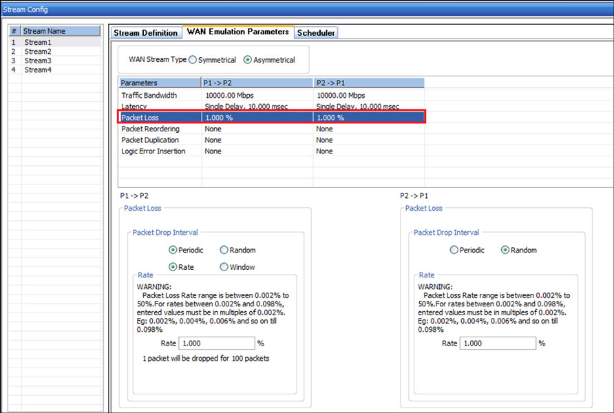
Packet Loss model configurations
Packet Reordering
Packet reordering model includes Periodic and Random Packet Reordering options. In Periodic option, the packets are reordered at constant specified rate. While in Random option, packets are randomized for reordering, but still maintain the specified Reorder rate.
Once a packet has been selected for reordering, it will be held for a certain amount of time before being reinserted into the stream. The delay can be configured in terms of time (milliseconds), or Packet offset (number of frames). During Packet offset delay, the reordered frame will be held until the configured offset frames are received, before being reinserted into the stream. The offset selected at run time will be a random value between the maximum and minimum defined value range.
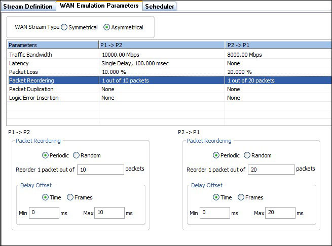
Packet Reorder model configurations
Packet Duplication
Packet Duplication model also includes Periodic and Random Packet Duplication options. In Periodic Duplication option, the packets are duplicated at specified rate periodically. In Random Duplication option, the selected packet is duplicated (based on the rate) randomly, but maintaining the duplication rate.
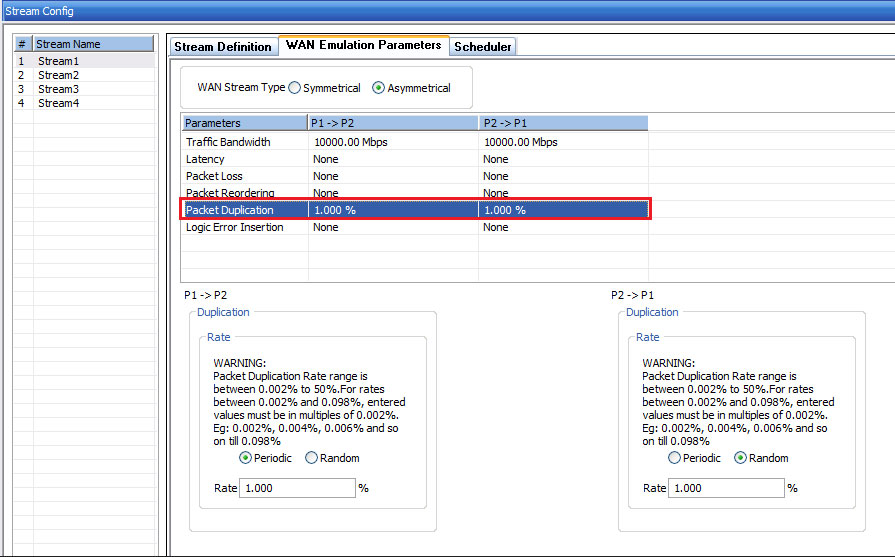
Packet Duplication model configurations
Packet Error Insertion
Packet Error Insertion model also includes Periodic and Random Packet Error Insertion options. In Periodic Error Insertion option, the start of frame and end of frame byte offsets specifies where exactly in the frame to inject errors. In the Random Error Insertion option, the packet will be randomly selected for error insertion (based on the rate), but the error insertion rate is maintained.
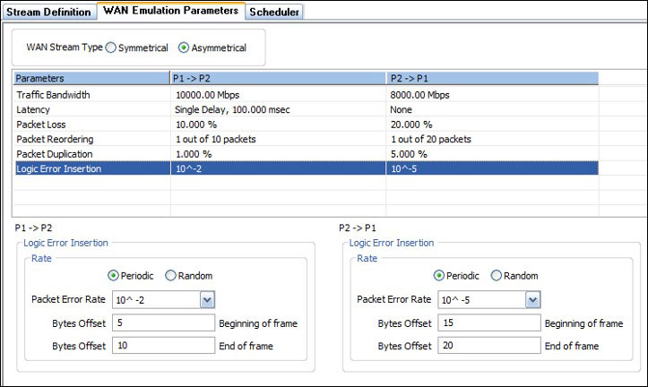
Packet Error Insertion model configurations
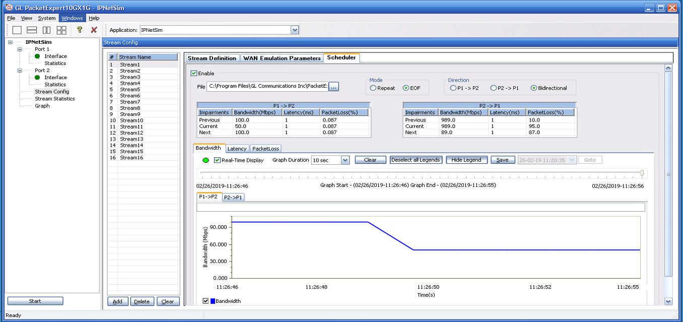
Impairment Scheduler
PacketExpert™ includes Scheduler feature to automate stream impairment. Scheduler reads Packet Loss(%), Latency(msec), and Bandwidth(Mbps) impairment values from a compatible csv file (generated from MTGA application) for both the link directions (P1→P2) and (P2→P1), which can be used to impair the selected stream. The applied impairment for each stream can be viewed graphically as well.
The following is the Bandwidth (Mbps) graph plotted against Time (Sec) for the selected stream as per the values defined in the csv file.
WAN Link Impairments
GL's IPLinkSim™ WAN link emulator is capable of emulating a WAN link, and introducing typical WAN impairments like Bandwidth Throttling, Latency, Jitter, Packet Loss, Packet Reordering, Packet Duplication, Packet Corruption, Logic and FCS Error Insertion.
IPLinkSim™ supports single stream only and applies the impairments to the traffic. In addition to the impairments in multi-stream (IPNetSim™) application, IPLinkSim™ also supports congestion emulation by generating background traffic.
The link emulator has the capability to better model real-world impairments with Periodic and Random options, which are briefly discussed below:
Bidirectional WAN link Emulation
Packet Loss Impairment
Packet Loss can be introduced either Automatically or Manually. For both automatic and manual, user can choose to drop a single packet or a burst of packets, at a time.
- Automatic Packet Loss: Loss rate can be configured to determining the frequency at which packets are dropped. There are two options available: Periodic loss and Random packet loss. In periodic loss, packet drops occur at regular intervals, making the loss predictable. On the other hand, random packet loss involves packets being dropped randomly without any specific pattern. In both cases, the overall packet loss rate remains the same, but the method of selecting which packets to drop differs
- Manual Packet Loss: This allows user to manually drop either a single packet or burst of packets at run time. This drop will be in addition to the rate loss, if active
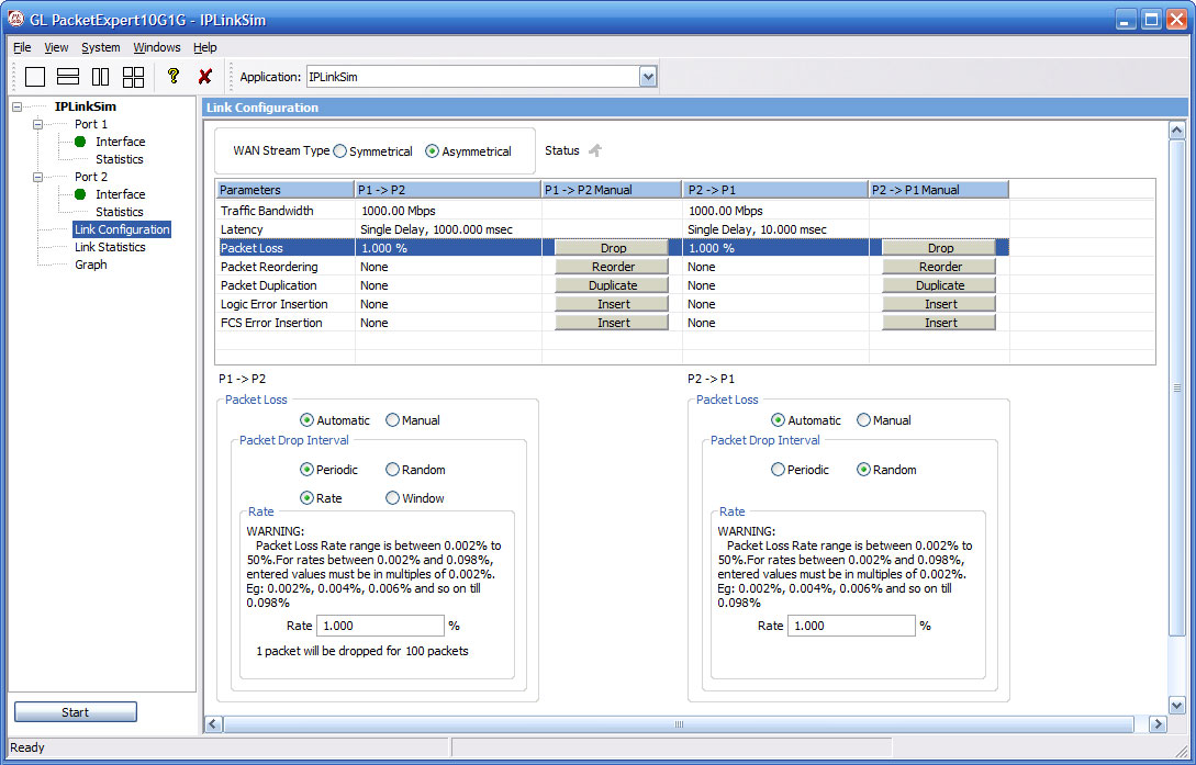
Packet Loss model configurations
Packet Reordering
Packet reordering can be done either Automatically or Manually. An Automatic packet reordering model includes Periodic and Random Packet Reordering options. In Periodic option, the packets are reordered at constant specified rate. While in Random option, packets are randomized for reordering, but still maintain the specified reorder rate.
Once a packet has been selected for reordering, it will be held for a certain amount of time before being reinserted into the stream. The delay can be configured in terms of time (milliseconds), or Packet offset (number of frames). During Packet offset delay, the reordered frame will be held until the configured offset frames are received, before being reinserted into the stream. The offset selected at run time will be a random value between the maximum and minimum defined value range.
The Packet Reordering model also includes Manual Packet Reorder option to reorder a packet instantaneously at run time. When selected, it will immediately reorder a single packet.
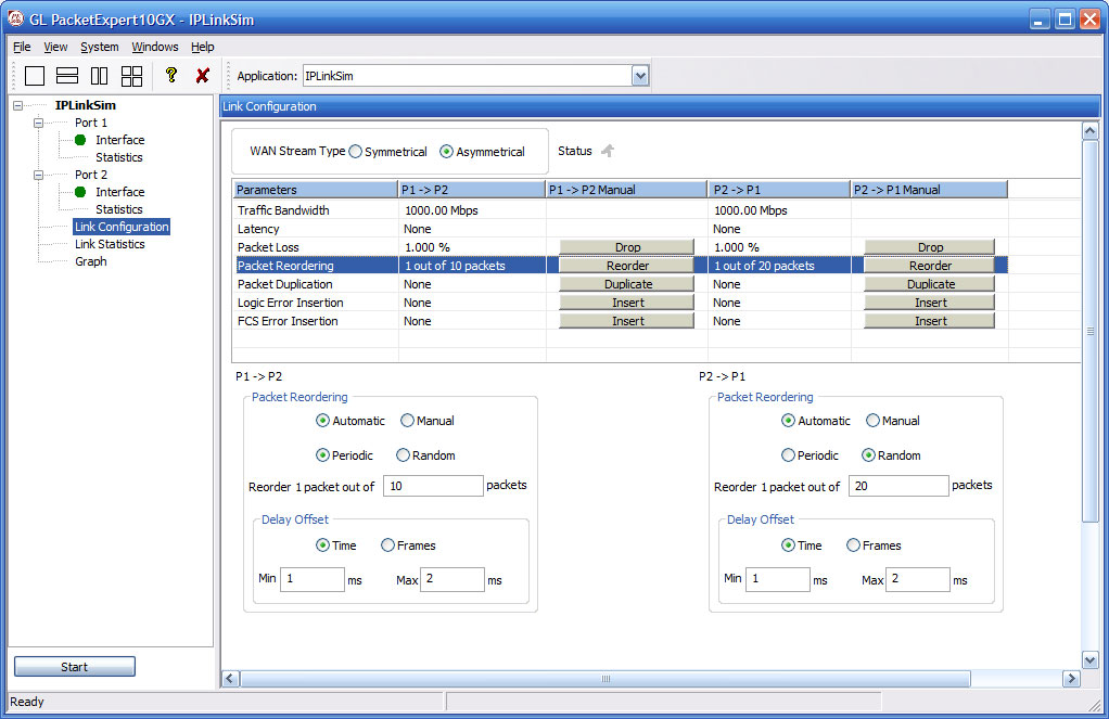
Packet Reorder model configurations
Packet Duplication
Packet duplication can be achieved through two methods: Automatic and Manual.
The Automatic Packet Duplication model provides two options: Periodic Duplication and Random Packet Duplication.
In Periodic option, packets are duplicated at a specified rate in a periodic manner. This means that packets are systematically copied at regular intervals according to the specified duplication rate.
In Random option, packets are randomly selected for duplication based on the specified duplication rate. This introduces variability in the duplication process while ensuring that the overall duplication rate remains consistent.
The Manual Packet Duplication option allows for instantaneous duplication of a single packet during runtime. This provides the flexibility to selectively duplicate specific packets as needed.
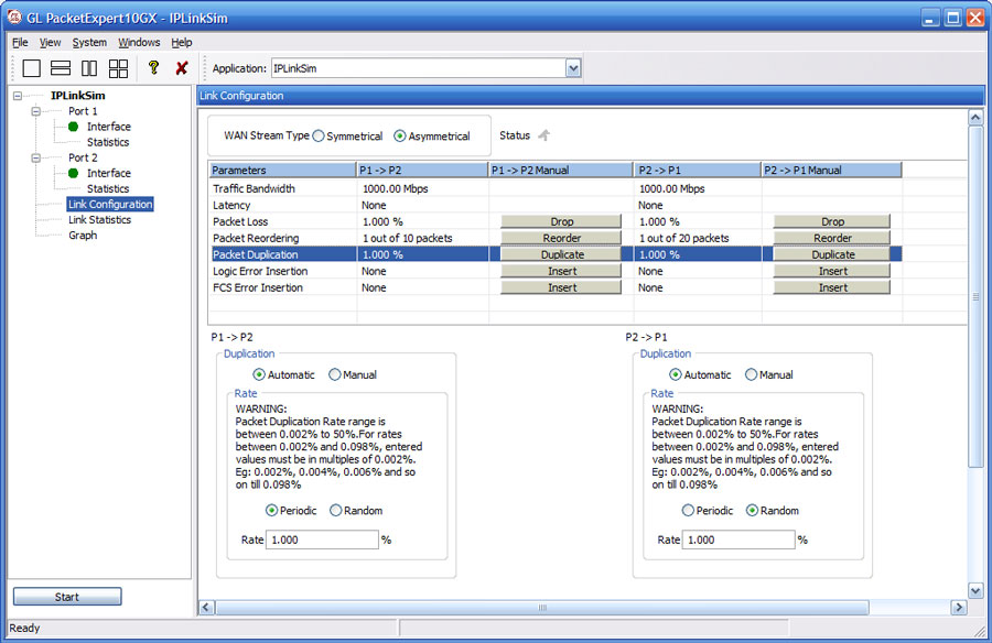
Packet Duplication model configurations
Packet Error Insertion
The Packet Error Insertion model provides users with both Automatic and Manual error insertion options.
Automatic Error Insertion offers two methods: Periodic Error Insertion and Random Packet Error Insertion. In the Periodic Error Insertion option, users can specify the byte offsets at the start and end of the frame where errors will be injected. This allows for precise control over the location of error insertion within the frame.
In the Random Error Insertion option, packets are randomly selected for error insertion based on the specified error insertion rate. However, the overall error insertion rate is maintained consistently.
On the other hand, the Manual Error Insertion option allows users to manually introduce errors into a single packet during runtime, providing flexibility and control over the error injection process.
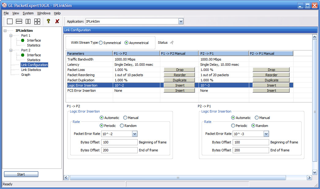
Logic Error Insertion model configurations
FCS Error Insertion
Frame Check Sequence (FCS) refers to additional checksum characters that are added to a frame to detect errors. This feature allows users to simulate errors that typically occur due to interference, incompatible devices, or edge devices like gateways. In this scenario, the FCS bytes within the frames are intentionally corrupted.
Users have the choice to insert FCS Errors automatically or manually
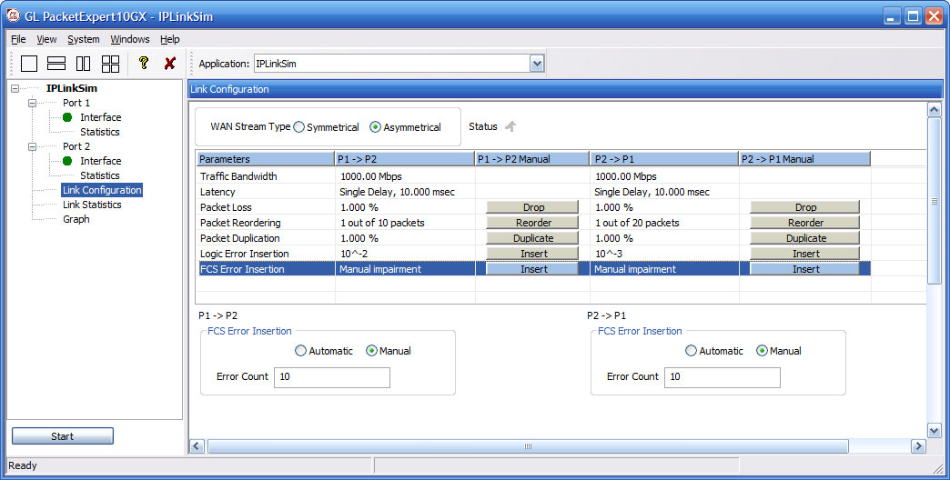
FCS Error Insertion Model Configurations
Testing Satellite WAN Links
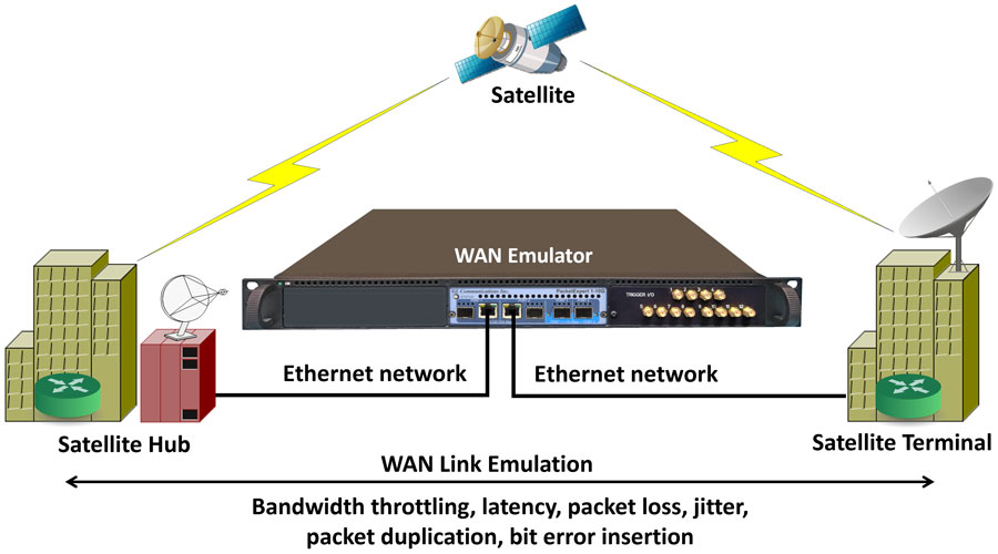
Application performance over WAN networks can be highly sensitive to bandwidth, latency, jitter, loss, and other WAN impairments. Testing these applications on the local network generally fails to identify critical issues that impact the end user experience. Fortunately, GL provides a WAN network emulation appliances that makes it simple and affordable to test applications in the lab under real-world conditions, ensuring smooth roll-outs of new applications and helping to optimize the performance of the applications for the end-users.
Resources
| Item | Description |
|---|---|
| PXN100 | PacketExpert™ 10GX |
| IPN507 | IPNetSim™ & IPLinkSim™ Options for 1G, 2.5G and 10G |
| Brochures |
|---|
| Presentations |
|---|
Webinar

Comprehensive Ethernet Testing Solutions
WAN Impairment Simulation for Packet and TDM/Analog Networks

Wide Area Network Emulators IPNetSim™ 10G & 1G