Overview
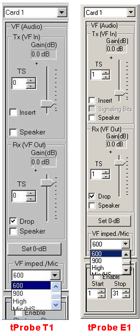
This application permits any single timeslot to be decoded to the VF Output jack, i.e. the PCM signal in a timeslot is converted to analog and fed to the VF Out jack. This signal can also be fed to an onboard speaker. The VF Dialog Bar also allows you to control the gain of the signal.
Similarly, an analog signal can be fed to the VF In jack for insertion into any timeslot. The applied signal can be attenuated or amplified before analog to digital conversion using the gain setting.
An integrated 4-wire handset connection is provided for portable USB Units. For PCI Ultra cards an external handset adapter is provided, that in turn connects to the VF Input and Output.
tProbe™ analyzer have individual speakers for Tx & Rx per card, in addition, both can be used simultaneously.. The portable USB Units have only one speaker. For portable USB if the speaker is checked on for both receive ports, then the audio is combined and fed to the speaker.
VF Drop and Insert
In the Drop and Insert mode, the timeslots selected are dropped and the selected pattern is inserted into the selected timeslots.
Examples using VF Dialog bar
- Example 1
- Cross connect port 1 and port 2 of T1/E1 cards; connect a four-wire handset either through the direct handset connection on portable USB unit or through the handset for PCI Ultra Cards (for PCI cards, connect the IN on handset adapter to the OUT of any card (1) and OUT on handset adapter to the IN of the same card (1). Connect the handset to the adapter jack.
- Enable timeslot 1 on VF 'INSERT' of card1. Open the power Spectral Display on timeslot 1 of card2, and enable the speaker in VF dialog bar. Speak through the handset. The spoken voice should be indicated on the spectral display as well as should be heard in the speaker.
- Experiment similarly other timeslots.
- Example 2
- Cross connect port 1 and port 2 of T1/E1 cards.
- Transmit a tone on any timeslot using the transmit tone application, and listen to the tone using a speaker or a handset with VF dialog Bar application.
- Example 3
- Cross connect port 1 and port 2 of T1/E1 cards.
- Cross connect VF Input to the VF Output. Set the VF Output to decode on timeslot 1 and the VF Input to encode onto timeslot 2.
- Transmit a tone on timeslot 1 using the transmit tone application; also setup two Spectral Displays to observe the returned tone on timeslot 2 and timeslot 1. Note that the S/N ratio on the tone returned on timeslot 1 (digitally) is around 39 dB, whereas, the S/N on timeslot 2 is about 36 dB. The degradation is due to successive D/A and A/D conversions.
VF Input and VF Output Signal Flow
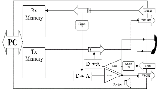
The block diagram below shows the flow of data relevant to VF Input and VF Output. Please note the following features:
- A four-wire handset is connected to the handset connection provided on portable USB units.
- A handset adapter is required for PCI/HD Ultra Cards in which case the VF Input and VF Output jacks are used.
- Only a single (selected) timeslot can be decoded to audio (VF Output); analog gain may be applied prior to output to speaker and VF Output.
- Only a single (selected) timeslot can be encoded (VF Input); analog gain may be applied prior to the encoding.
- The VF Output may be fed to the PC speaker for greater fidelity and volume, if desired.
- USB and Universal analyzers use 3.5 mm mono connections on VF ports. tProbe™ analyzer uses a 3.5 mm stereo/balanced connections on VF port. For more details refer: VF Input/Output Interfaces for T1 / E1 Products.
Data Drop and Insert
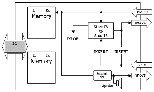
The drop and insert function loops incoming data back to the output except for the timeslots that are dropped. The drop and insert operation requires that the transmit clock be set to "recovered clock" otherwise data will not be inserted correctly into the outgoing stream
Inserted data is taken from the Tx Memory, which is controlled by the PC software; files may be transmitted into the dropped timeslots or any other software generated signal. VF Insert and VF Output operate independently of the Data Drop and Insert option.
Example
- From an external source (separate from the unit under test) supply a T1/E1 signal to the T1/E1 input of the unit under test.
- Enable drop and insert (at the bottom of the VF Dialog Bar) on the unit under test. Set the start and end timeslots to 5 and 17, respectively.
- Verify that the signal from the external source looped back out to the source on timeslots 0 to 4 and timeslots 18 to 23 (for T1).
- Verify that tone or files can be inserted into the dropped timeslots.
 Back to List of T1E1 Basic and Optional Applications Index Page


