T3/E3 Interface Configuration
Framing Formats for T3

M13, C-Bit, Unframed - T3 Framing Formats
M13 Framing Format
The M Frame format was originally designed for multiplexing 28 T1s. Today however the M13 format can be used for channelized or un-channelized data. Channelized data can either be data from multiplexed T1s or data that is subdivided to provide multiple or single high speed data channels that are a fraction of the T3 payload data (from the 84 payload data chunks that accompanies each block).
C-Bit Framing Format
The C-Bit Parity framing format is an enhancement of the original M13 application. The main difference is the C-Bit Framing format always stuffs the 1st bit of the 8th block in each subframe. This means that the use of the C-Bits for their original stuffing function would be redundant. Therefore, in C-Bit format the C-Bits can be used for greater management and performance functions on the M frame.
M13 Vs C-Bit
The two main framing formats that are found on T3 lines are M13 and C-Bit parity. C-Bit parity offers all the same functions as M13 with further enhancement in the ways of a remote communications link, better error performance methods, and local transmissions to remote errors and loopbacks via the FEBE, TDL and FEAC functions. All in all if given a choice, the user should choose the C-Bit parity format.
Another item of note between the two formats, is that the C-Bit parity format uses stuffing all the time, where the M13 framing format uses the C-Bits to identify stuffing in particular T2's.
Framing Formats for E3

Framed and Unframed - E3 Framing Formats
Framed: The transmitter and receiver are set to for framed E3 data.
Unframed: The transmitter and receiver are set to for unframed E3 data.
T3/E3 Loopbacks

Outward and Diagnostic Loopback options
Loopback capability between the local T3/E3 interface and the remote CSU are used to diagnose problems with the T3/E3 analyzer or with the CSU when it is isolated from the network. With this feature all the received data can be looped back to the transmitting port for analysis.
This option has various loopback modes as explained below
No loopback (Loopback=None)
This option disables any existing loopback conditions. With the no loopback configuration, the T3/E3 controller sends a DS3/E3 idle signal towards the network.
Outward Loopback (Line Loopback)
In this configuration the data sent from the CSU are received by the T3/E3 interface and are immediately retransmitted to the CSU.
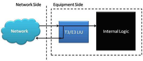
Logical Diagram for Outward Loopback
Diagnostic Loopback (Inward Loopback)
The Diagnostic Loopback option is used to activate a diagnostic loopback, which loops the outgoing T3/E3 signal back into the card at the T3/E3 Line Interface Unit (LIU).
With diagnostic loopback, the T3/E3 interface can transmit packets to the network, but receives its own transmission back. In this mode the receiver will not recognize the data from the network.
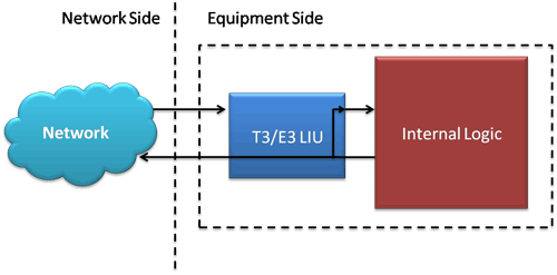
Logical Diagram for Inward Loopback
T3/E3 Rx Signal Setup- Terminate, and Monitor

Terminate and Monitor Rx Signal options
This option configures the board for the T3/E3 input level depending on user requirements.
Terminate
This option terminates the input T3/E3 signal (the signal connected from DSX jack on a T3/E3 patch panel) using impedance.
Monitor
The incoming signal is a low power DSX-3 Monitor signal with this option.
T3/E3 Clock Source
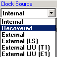
Clock Source options
The clock source option is used to select the timing reference for the outgoing T3/E3 signal. Refer the diagram for explanations on various clock source settings.
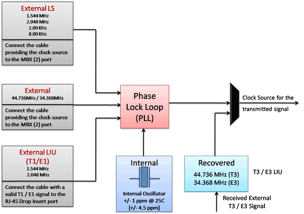
Logical Diagram for Clock Source options
Internal (line timing)
Internal is used to set the outgoing T3/E3 signal rate by an on-board T3 - 44.736 MHz and E3 - 34.368 MHz oscillators. In this mode, the simulator provides the master timing for the outgoing signal.
Recovered
Recovered is used to recover the clock from the incoming T3/E3 signal. The outgoing signal runs at the same rate as the incoming signal.
External
In this mode, an external clock signal is used as the master clock. Connect the cable providing the clock source (44.736 MHz for T3 or 34.368 MHz for E3) to the MXB (2) clock port.
External (LS)
In this mode, the card can accept a low speed (LS) frequency clock source as shown below:
- 1.544 MHz
- 2.048 MHz
- 2.00 kHz
- 8.00 kHz
The PLL can detect any one of the above frequencies and then generate the T3/E3 frequency from the supplied low speed frequency. As in the case of External clock settings, connect the cable providing the clock source to the MXB (2) clock port.
External LIU (T1) & External LIU (E1)
The T1/E1 External Clock input enables the retrieval of clock reference from a T1 or E1 signal. In this mode, connect the cable carrying a valid T1/E1 signal to the RJ-48c port.
T3/E3 Modes Selection
Unstructured Mode
The unstructured (unchannelized) mode identifies the data stream as a large group containing the entire T3 bandwidth. This mode is basically used for high speed data applications.
Structured Modes
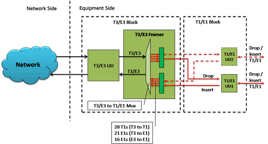
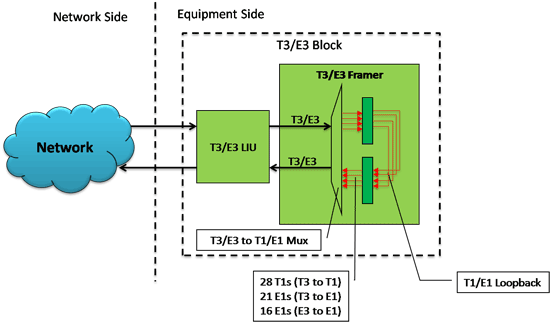
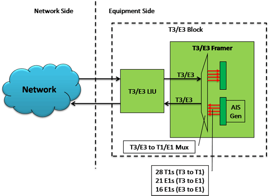
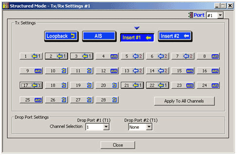
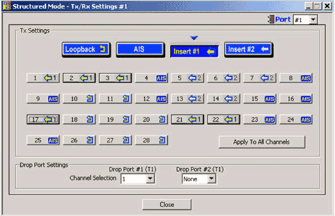
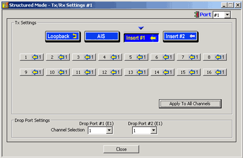
Up to two user selected T1 (or E1) channels can be externally inserted using the T1/E1 input/output interface into any one of the transmitted T3 or E3 signal. The inserted T1 or E1 signal can be selectively transmitted through one or more of the T1/E1 transmit channels, or broadcasted through all the T1/E1 channels. Additionally, the received T1/E1 signal can be looped back and transmitted or the transmitted T1/E1 signals can be set to carry AIS.
Drop Insert Settings For T3 Systems
The T3 transmitter can multiplex individual T1/E1 bit streams into the T3 signal. Similarly the T3 receiver can demultiplex individual T1/E1 bit streams and drop it through the drop port.
Drop Insert Settings For E3 Systems
The E3 transmitter can multiplex individual E1 bit streams into the E3 signal. Similarly the E3 receiver can demultiplex individual E1 bit streams and drop it through the drop port.
 Back to List of T3E3 Basic and Optional Applications Main Page


