Newsletter: GL Enhances T1 E1 Jitter and Pulse Mask Measurement Solutions
Welcome to another June 2011 issue of GL's Newsletter providing information on our Jitter Measurement and Pulse Mask Testing solutions.
Jitter Measurement
Jitter along with wander and frequency drift are major impairments of clocks in synchronous systems. Jitter is the time discrepancy between the time of arrival of a clock pulse and its theoretical arrival time. Jitter arises from a number of sources, including aging of clock circuits, thermal and loading effects, Doppler shifts, and de-multiplexing from higher bit rate data streams.
GL's Jitter Measurement module allows evaluation of jitter on either a tick-by-tick or a cumulative basis. Technically, cumulative jitter is of primary importance as network equipment must cope with the cumulative jitter. However, tick-by-tick measurements are also presented in this module.
Since clocks under test can have arbitrary clock rates, it is customary to talk about jitter in terms of the time duration of a single clock pulse. This time interval is referred to as a "Unit Interval" or UI. For T1 systems operating at 1.544 Mbps, 1 UI equals 647 nanoseconds. For E1 systems operating at 2.048 Mbps, 1 UI equals 488 nanoseconds. UI durations for higher rate bit streams are proportionately smaller.
Important Jitter Measurement Features
- Easy, accurate, visual pulse shape and jitter measurement for T1/E1 signals (only available with Universal T1/E1 cards and tProbe™ T1/E1 analyzer).
- Provides an option to select T1 or E1 port for monitoring and the frequency range of interest.
- Supports One-Shot capture and Repeated Capture options for jitter measurement.
- Jitter generation (coming soon)
For further information, please refer to Jitter Measurement web page.
WCS Jitter Measurement
The Jitter measurement can be performed through commands with the Windows Client-Server application. The jitter ranges can be monitored on a specified port using simple commands by a client application.
For further information, please refer to WCS Jitter Measurement web page.
Pulse Mask Compliance Testing
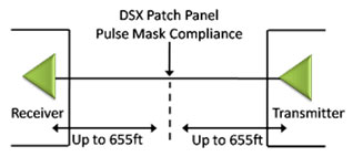
It is quite common for T1 E1 signals, within a central office environment or an enterprise telecom room, to NOT meet pulse mask requirements due to interference, too long or short cable lengths, improper impedances, or simply poor transmitter design. In such cases, pulse mask compliance is very useful in diagnosing problems.
GL's tProbe™ T1/E1 Analyzer and Universal T1 E1 Cards have pulse shape measurement capability. Software has been developed to determine if the pulse shape fits within a "pulse mask" as specified by standards ITU G.703 and ANSI T1.102-1993. The software is available in both visual and tabular formats. Tabular formats are convenient for automation and scripted test environments.
Important Pulse Mask Compliance Features
- Plots the pulse measured within a predefined template.
- Compares the incoming T1/E1 pulses against the pulse mask display.
- For T1 pulses, the x-axis measures time in unit intervals (UI), while for E1 pulse, the x-axis measures time in nanoseconds (ns),
- The y-axis measures the normalized amplitude in volts.
For further information, please refer to Pulse Mask Testing web page.
WCS Pulse Mask Testing
The Pulse Mask Client-Server application in Universal boards is used for detection, monitoring, and plotting of transmitted pulses. Some of the commands supported are CheckPulseMask, validate pulse, stop pulse mask validation, and others. Pulse Mask will also return all error and warning message to WCS client as task error or warning message.
For further information, please refer to WCS Pulse Mask Testing web page.
 Back to Latest News Page