Analog Legacy Protocol Enhancements
26th, Apr 2019
Welcome to another April issue of GL Communications' Newsletter providing information and insight into our T1 E1 Protocol Analyzer software supporting legacy protocols (CAS – MFCR2, E&M, SS1/SS4, SS5) analysis and emulation– applicable to Federal Aviation Administration "FAA" within their National Airspace System "NAS" Ground-to-Ground Air Traffic Control Network and Voice System (NVS) to Analog Interphone.
Overview
Signaling that occurs between switches (such as PBXs, local exchange carrier and interexchange carrier) in telephone networks is sent either within the voice traffic or on a separate dedicated signaling channel.The Channel Associated Signaling (CAS) is a method of signaling where a channel or timeslot carrying speech also carries with it the signaling and addressing to set up and tear down calls. This supervisory signaling is carried as "on-hook" and "off-hook". The addressing is carried as DTMF (Dual Tone Multi Frequency) or as MF (Multi Frequency). This form of signaling is still used to route calls on the public switched telephone network (PSTN) including subscriber lines like 2wire local loops, on trunks between central offices (CO), and on access trunks such as PBXs.
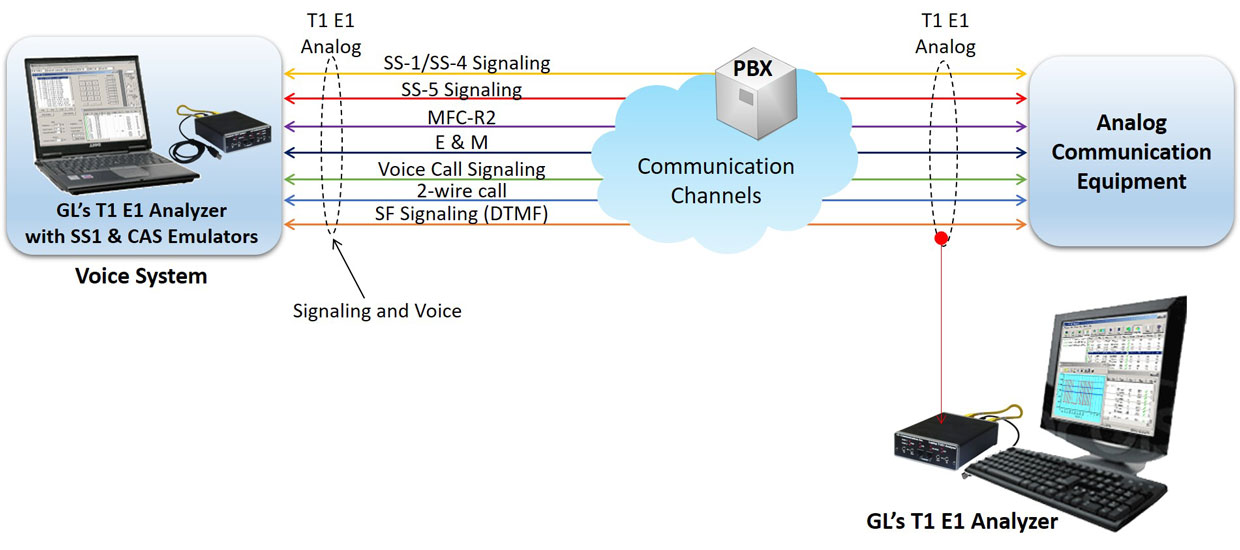
GL’s CAS and SS1 legacy protocol test solution supports simulation and analysis of Signaling and voice communications interface between the National Airspace System (NAS) Voice System (NVS) and the legacy NAS Voice Switches, utilizing Ground to Ground (G/G) trunks that support Analog interphone call processing.
GL's T1/E1 Cards and USB units provide T1 and VF I/O jacks through which one can monitor or inject audio signals from or onto a designated T1 timeslot, or VF line. The T1/E1 hardware test platform along with Analyzer and Emulator supporting legacy protocols can generate Selective SS-1/ SS-4, SS-5 Signaling, Voice Call Signaling, 2-wire Call, Single Frequency Signaling, MFC-R2 Analog, E and M signaling types of signaling and voice being carried over communication channel and is also capable of analyzing these signaling in real time.
Legacy Protocols Simulation
SS1 (Selective Signaling 1) Protocol Analyzer
Selective Signaling "SS-1" is a 2 and/or 3-digit dial system used by the Federal Aviation Administration "FAA" within their National Airspace System "NAS" Ground-to-Ground Air Traffic Control Network. It is used on leased and FAA lines between the Air Route Traffic Control Center's "ARTCC", Terminal Radar Approach Control "TRACON", Air Traffic Control Tower's "ATCT", Lockheed Martin Flight Service Hub's "FS-21", Military, National Weather Service and non-governmental aviation facilities for the control and management of aircraft flights.
GL’s T1 E1 test platform supports selective signaling in accordance with FAA-STD-054 for the analog G/G interface. SS1 Emulator (Dialer) application provides the ability to setup and dial tone sequences that make up SS1 dial digits. SS1 Analyzer detects and analyzes tone sequences that make up SS1 dial digits. Sequences of pulse and guard tones are detected, decoded, and assembled into their corresponding dial digits. The tone sequences are also verified for compliance against a “specification” parameter which can correspond to published standards or user criteria.
GL’s T1 E1 test platform supports selective signaling in accordance with FAA-STD-054 for the analog G/G interface. SS1 Emulator (Dialer) application provides the ability to setup and dial tone sequences that make up SS1 dial digits. SS1 Analyzer detects and analyzes tone sequences that make up SS1 dial digits. Sequences of pulse and guard tones are detected, decoded, and assembled into their corresponding dial digits. The tone sequences are also verified for compliance against a “specification” parameter which can correspond to published standards or user criteria.
SS1 Analyzer Detecting and Analyzing Dial Code
SS1 Dial Code in a Waveform Viewer
MAPS™ CAS Single Frequency Signaling Emulator
In analog circuits, channel bandwidth is divided into a 300 – 3400 Hz “voiceband” used for speech and/or data, and a “supervisory band” centered at 2400/2600/2800 Hz used for the signaling tone. Because both the supervisory signal (SF Tone on Idle and Active modes) and line traffic are carried in the same channel, filters are normally required at each end of the connection to separate out the line signal from the voiceband traffic.
MAPS™ CAS Single Frequency (SF) simulator can generate signaling tone on Idle and Active Modes with configurable operational frequency (2400/2600/2800 Hz) bands for analog G/G interface. It also has efficient filters to extract Voice from line signals and filters to inform the state of the remote-end efficiently.
Other related features include -
- Selection to SF signaling on Idle and Active mode operation
- User configurable Signaling Tone
- User control on call to Terminate, Answer, Reject calls
- Extracted voice can be recorded
- Ladder diagram for call flows
- Events window to keep track of the call status
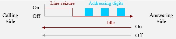
The following are the examples of Call Supervision in SF Tone on Active Mode and Idle Mode:
- The caller’s DTMF digits is superimposed on the signaling tone as it is inserted when seizing the channel.
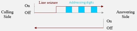
- The calling side seizes the line by dropping the signaling tone (Line seizure state). At this point, addressing tones are exchanged according to the signaling standard.
Voice Call Signaling Emulator
Voice call lines are typically used for four-wire, point-to-point, two-way voice calls. A Voice detect (VOX) circuit is used on the receive pair to detect incoming audio and signal the voice switch. No signaling is used on the transmit pair. These calls are sometimes configured on 2w circuits.
MAPS™ CAS supports Voice Call Signaling by providing voice activated circuitry (VOX) to control voice connectivity and ensure immediate activation of the circuit upon receipt of incoming voice. During out-going call, it seizes (open) any circuit designated by the Government as a voice call line and transmits the voice into the circuit, whenever the circuit is activated.
User configurable VOX threshold, exhibit a voice signaling threshold of -26 dBm0 (nominal test level) and blocks responses to voice signals below the threshold of -26 dBm0 for the analog G/G interface.
MFC-R2 Analog Simulation
GL’s MFC-R2 Analog implementation using MAPS™ CAS and WCS commands.
During outgoing call, the signaling tone and the MFR2 forward digits are sent using a sequence of tone commands. The signaling tone is removed when a call is placed and register signals are sent. While receiving MFR2 backwards digits superimposed on the signaling tone, will be separated into voiceband and signaling tone using band filters.
While simulating incoming call, MFR2 backward digits are superimposed onto the signaling tone without interrupting the signaling tone for transmission. The incoming signals can be decoded using standard WCS signal and digit detectors to monitor the receiving signals.
SS5/ATS-No.5 Call Simulation
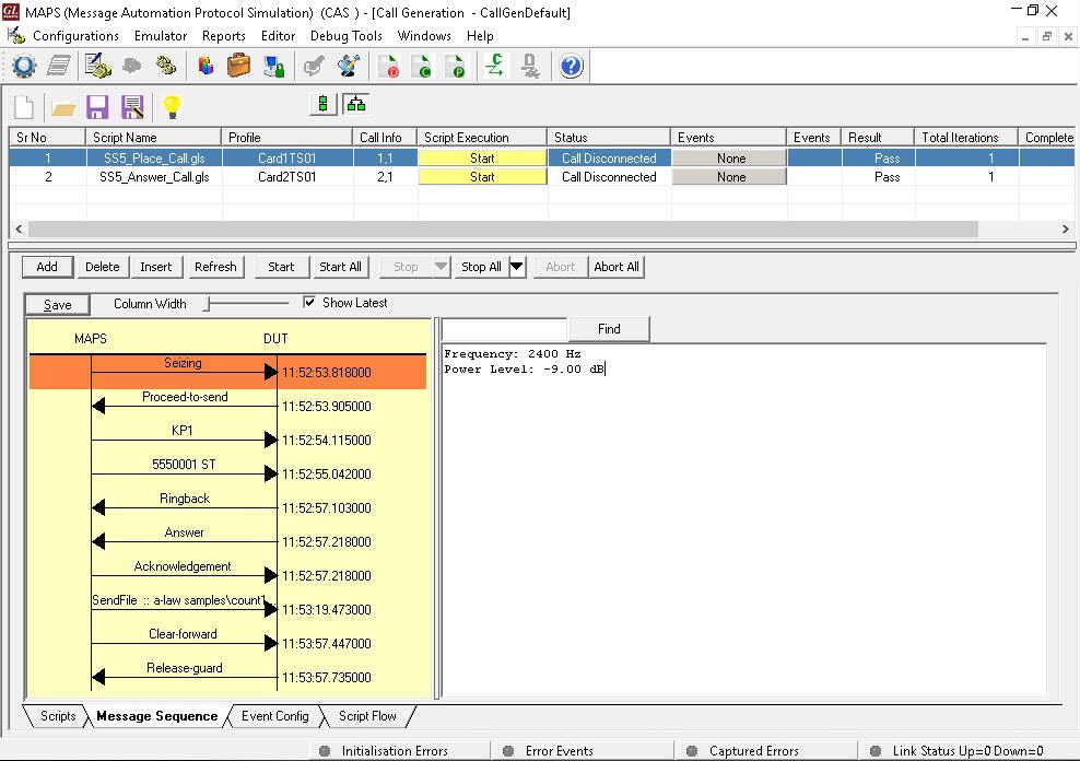
MAPS™ CAS supports Signaling System No 5 Line and register signaling procedure simulation as per Q.140- Q.199. SS5 specifications. SS5/ATS-No.5 call simulation is automated with ready-to-use scripts and facilitates to add events on active calls.
ATS-No.5 is a variant of SS5 signaling system, which is used in order to Seize a line, clear a line from either calling or called user side, block a line and answer a call. Line signals use one or two tones. VCSs are able to distinguish between different line signals by keeping track of the call state during the call setup or clearing procedure. Line signals can be sent from either side of an inter-VCS link. ATS-No.5-line signals are compelled implying that each line signal sent in one direction has a corresponding acknowledgement line signal in the opposite direction.
 Back to Newsletter Index Page