MAPS™ MEGACO Protocol Emulator
Media Gateway Control Protocol (MEGACO/H.248) is a signaling and call control protocol used between the Media Gateway Controller (MGC) and Media Gateway (MG) for supporting multimedia stream transmission.
Request a Demo / Quote BrochureOverview
The Media Gateway Control Protocol (MEGACO/H.248) is a signaling and call control protocol used between the Media Gateway Controller (MGC) and Media Gateway (MG) for supporting multimedia stream transmission. The MGC uses Megaco/H.248 to instruct MG about the events, media, signals to be played on Terminations, to create a Context, and to audit the status of the Terminations involved in the conversion of media from one type of network, to the media required in other type of the network.
GL’s MAPS™ MEGACO (H.248) Protocol Emulator supports Trunking Gateway and Residential Gateway simulation using binary based H.248 protocol and text based MEGACO protocol in Digital and Analog network respectively.
MAPS™ now supports both binary and textual encoding protocol versions. The binary encoding is based on Basic Encoding Rules (BER) description of the protocol and text encoding is based on Augmented Backus-Naur Form (ABNF) description. The MEGACO/H.248 protocol is implemented in binary encoding over 2G/3G core network. However, it can be still used in traditional text based encoding in IP networks as well. It is typically used for providing Voice over Internet Protocol (VoIP) services like voice and fax between different networks – such as IP Networks and the PSTN, IP Networks and Wireless Networks (2G/3G) or entirely within IP Networks.
The MAPS™ MEGACO (H.248) also supports Conformance Scripts (requires PKS123 licenses), which includes 200+ test cases as per Megaco specification of ETSI TS 102 374-2 document. Test suite includes in-built scripts which tests the functionality of the Media Gateway for Megaco protocol valid and in-valid behaviour.
With the purchase of RTP Core license (PKS102), MAPS™ MEGACO supports transmission and detection of various RTP traffic such as, digits, voice file, single tone, dual tones, IVR, FAX*, and Video*. With regular RTP traffic, the maximum Simultaneous Calls up to 2500, and Calls per Second up to 250 is achievable. Almost all industry standard voice codec supported.
GL’s MAPS™ MEGACO is also available in High Density version (requires a special purpose network appliance and PKS109 RTP HD licenses). This is capable of high call intensity (hundreds of calls/sec) and high volume of sustained calls (tens of thousands of simultaneous calls/platform).
GL also offers MAPS™ Media Gateway Controller (MGC - PKS300), a multi interface simulator is configured to handle call control between the Signaling Gateway (SG) and Media Gateway (MG) in the network to perform end-to-end test scenario by simulating SIGTRAN, MEGACO and MGCP interfaces. GL recommends purchasing additional MG simulation with appropriate RTP licenses for high density traffic simulation.
** Some of these traffic types requires additional licenses – contact GL for more information
Features
Signaling |
|
Codec |
|
Traffic |
|
High Density Call Capabilities* |
|
Other GUI Features |
|
Conformance Testing |
|
CLI |
|
Applications |
|
Supported Protocols Standards
| Supported Protocols | Specification Used |
|---|---|
MEGACO/H.248 |
IETF RFC 3525 / ITU-T Recommendation H.248,
ETSI TS 102 374-2 (2004-11) |
MAPS™ Megaco (H.248) in Analog and Digital Network
Typical TGW Simulation Procedure in Digital Network
The Trunking Gateway, which lies between Switched Circuit Network (SCN) and Packet Network can be setup in the lab with GL’s MAPS™ Megaco (H.248) capable of generating more than 500 simultaneous calls using multiple T1 E1 cards. Normally, 24 calls on T1 interface and 31 calls on E1 interface can be generated, as per the number of timeslots available on the respective interface.
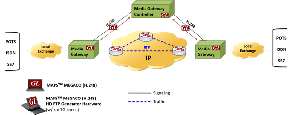
The following procedure illustrates call between two trunking gateways controlled via MGC. In this call scenario MGC generates messages for enabling media flow:
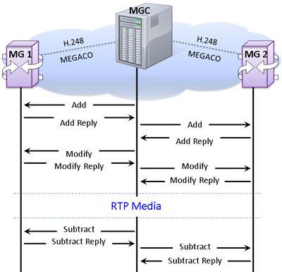
Trunking Gateway Simulation in Digital Network
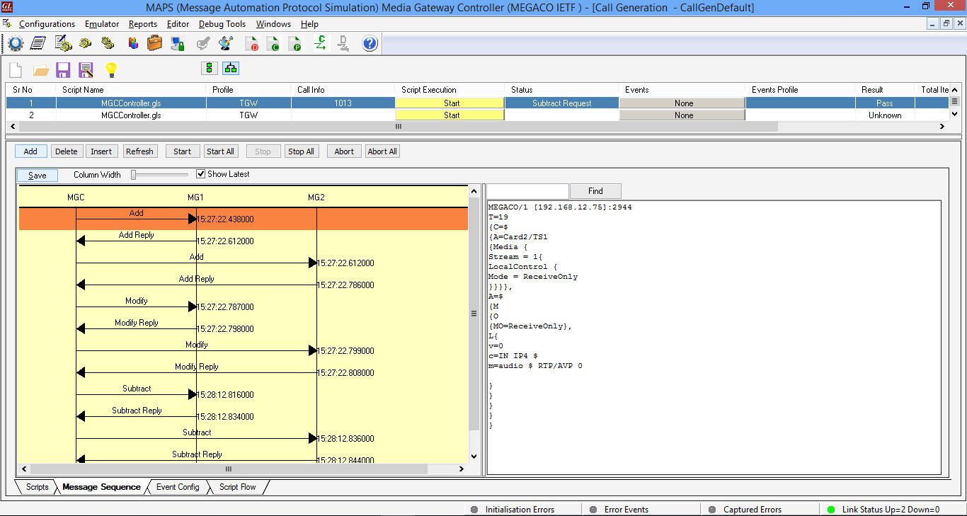
The following MAPS™ Call Generation GUI depicting the typical MEGACO (H.248) call scenario with binary and textual message decodes as shown below:
Typical RGW Simulation Procedure in Analog Network
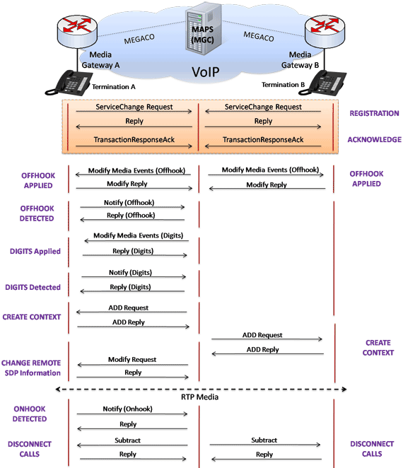
MAPS™ Megaco (H.248) can simulate Residential Gateway (RGW) containing one or two Analogue lines and is located at the customer premises that interworks an Analogue line to a Packet network. RGW simulation includes Analogue events and signals such as Onhook, Offhook, Detect Dialtone, Detect Dial Digits, Digits Generation of Ring and Busy tone, etc., which are required for call simulation. MAPS™ Megaco (H.248) is capable of generating more than 500 simultaneous calls simulating analog lines in the network.
Diagram below depicts the call flow scenario which is placed from one PSTN interface to another PSTN interface between two Media Gateways through IP Network.
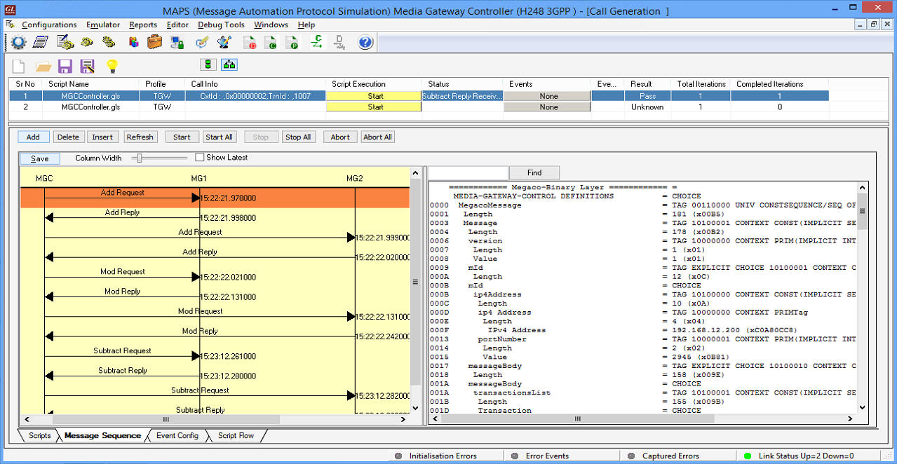
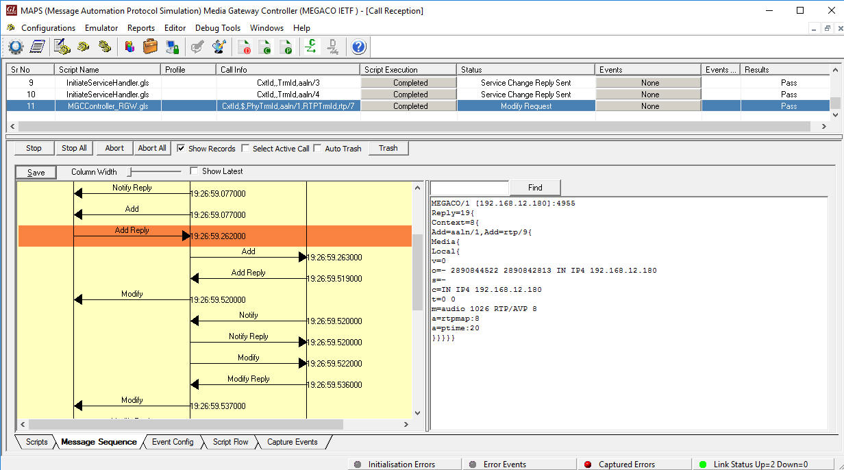
The following MAPS™ Call Generation GUI depicting the typical MEGACO (H.248) call scenario with binary and textual message decodes as shown below:
MAPS™ Megaco (H.248) in 2G 3G Network
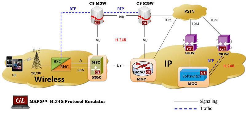
The above picture depicts MEGACO (H.248) in 2G, 3G CS core. The CS core network includes the MSC server, GMSC server and Media Gateways. The GMSC server and MSC servers are connected to the media gateway via the Mc interface. The H.248 protocol together with 3GPP specific extensions or packages is used over the Mc interface.
In a 2G/3G core network, the MSC server (or GMSC Server) acts as MGC and controls MG over a 3GPP interface, termed as Mc interface. The MSC (or GMSC) server supports the call control and mobility management functions, and the Media Gateway provides the bearer control and transmission resource functions. The underlying transport layer can be TDM, ATM, or IP.
GL's MAPS™ MEGACO (H.248) protocol emulator can simulate both MSC/GMSC (MGC) and MG network elements across Mc interface in 2G/3G and VoIP networks. The MSC servers and GMSC servers are connected via Nc interface. Any suitable call control protocol may be used over the Nc interface (e.g. BICC Protocol). The GMSC server and MSC server supports the call control and mobility management functions, and the media gateway provides the bearer control and transmission resource functions.
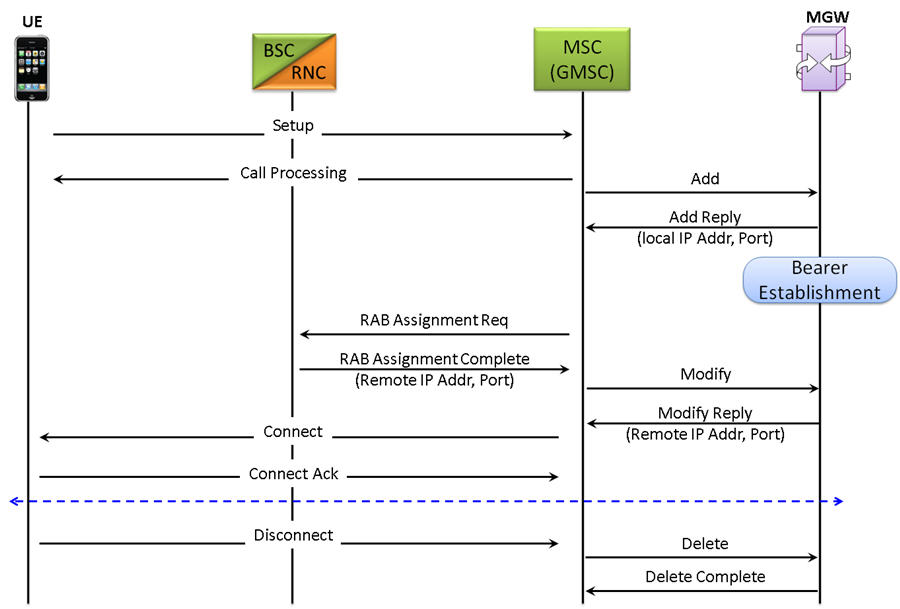
Diagram below depicts the H.248 (binary) call procedure which is initiated from the UE in the 2G/3G network and is processed at MSC/GMSC nodes communicating with the MGW handling the RTP traffic.
Call Simulation
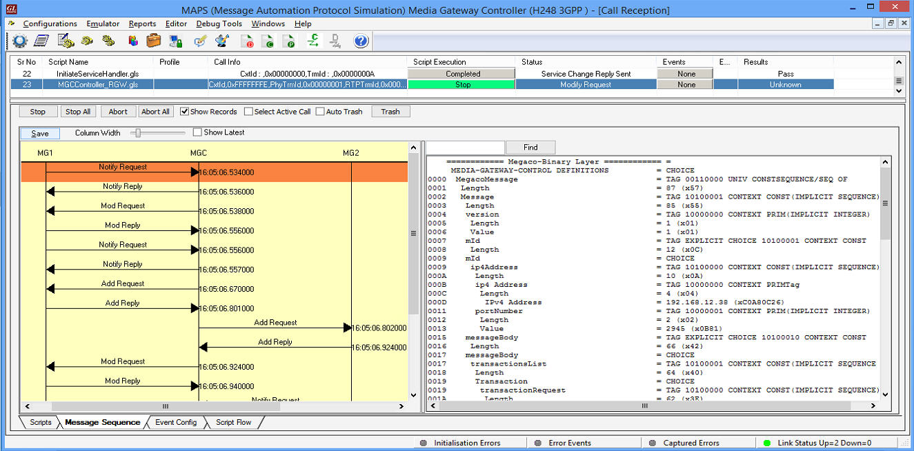
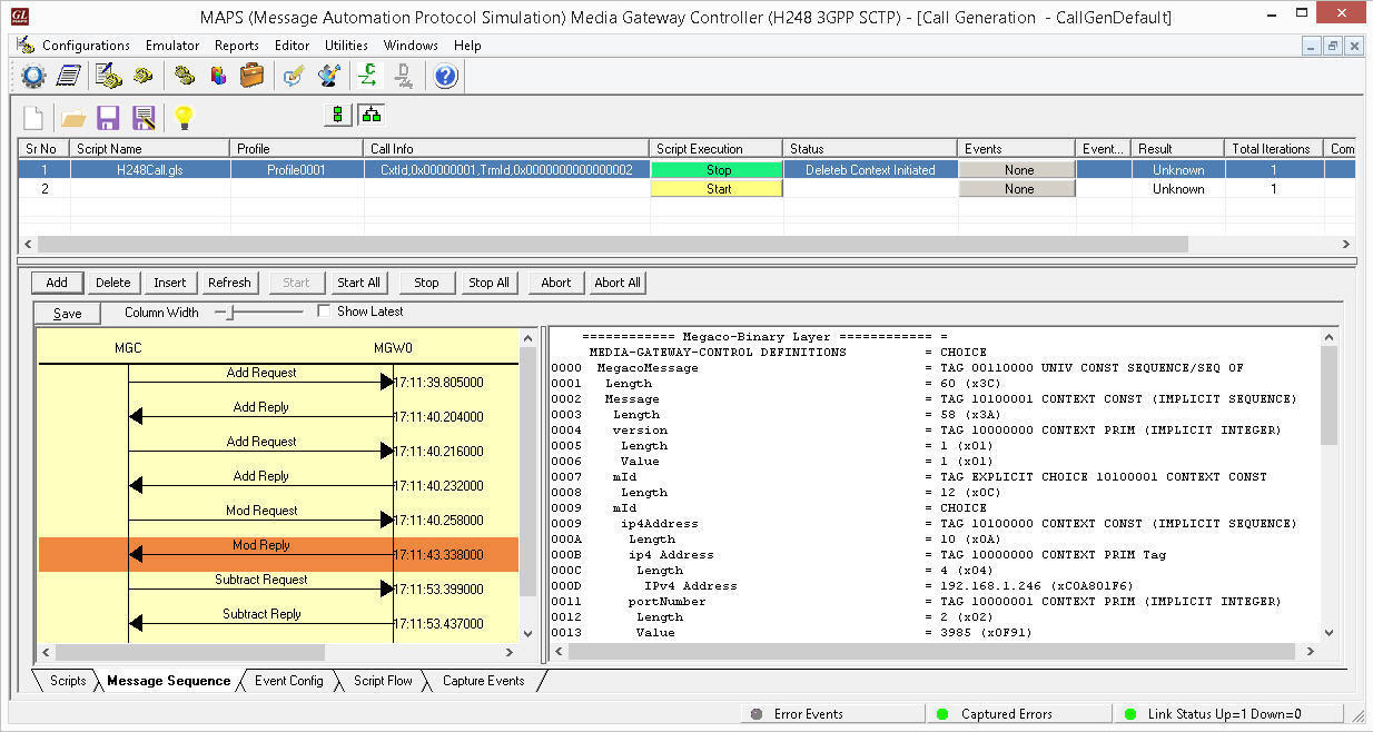
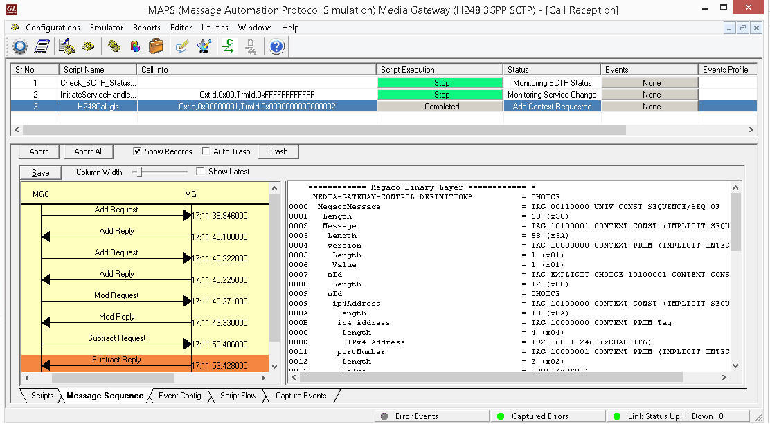
The following MAPS™ Call Generation application GUI depicts the typical Megaco/H.248 call scenario with binary message decodes:
MAPS™ H.248 Call Generation with Binary message decodes
MAPS™ Megaco Conformance
The MAPS™ MEGACO Conformance is designed with sample test cases, which equips the tool to act as MGC testing the functionality of the Media Gateway for Megaco protocol valid and in-valid behavior. MAPS™ receives registration requests from MG (DUT- third party gateway) and initiates the call flow.
MG Conformance Testing
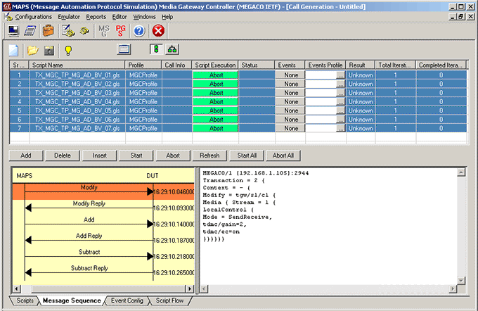
MAPS™ includes inbuilt Media Gateway conformance scripts (*.gls) that allow MAPS™ to act as MGC, so that entire MG (Media Gateway) testing can be automated. The device under test can be any Media Gateway. Users can control number of dumb Terminations in the Media Gateway through scripts.
For example, as shown in the figure below, the inbuilt TX_MGC_TP_MG_AD_BV_01.gls conformance script is executed to ensure that the DUT (MG) on receipt of MODIFY command request sends reply message.
MGC Conformance Testing
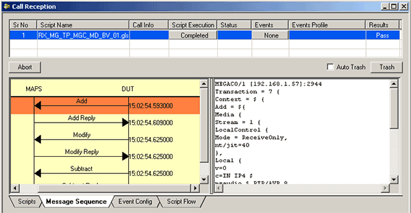
The inbuilt basic and conformance scripts allow MAPS™ to act as MG, and to test MGC (DUT).
For example, the RX_MG_TP_MGC_MD_BV_01.gls conformance script is executed to ensure that the MGC (DUT) sends ADD command and then the MAPS™ (MG) sends reply message.
End-to-End Gateway Testing
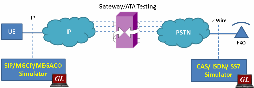
As shown in the figure below, MAPS™ is an ideal tool to evaluate Gateway / ATA product features such as call connectivity, call signaling, traffic generation, voice quality testing, codec, and hundreds of other features. For more details, contact GL Communications.
MGC Multi-Interface
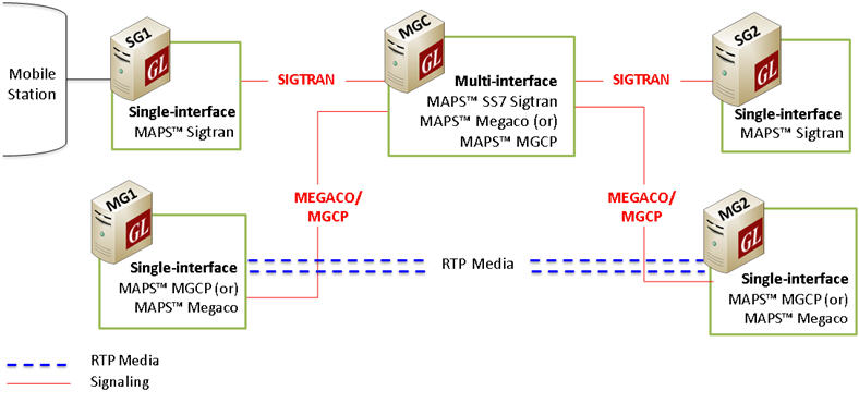
Multi-Interface Test Setup
MAPS™ Media Gateway Controller (MGC) a multi interface simulator is configured to handle signaling and call control between the Signaling Gateway (SG) and Media Gateway (MG) across the network. MAPS™ MGC simulates SS7 signaling procedure between the SGs on both the ends of the network while handling bulk traffic (RTP Media) between the MG terminals.
For the following test scenario, MAPS™ for Sigtran & Megaco (single interface application) can be configured as SGs and MAPS™ Megaco HD as MGs creating multi-interface network at MGC.
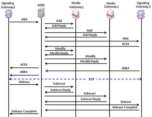
- SG1 initiates signaling towards SG2 over SIGTRAN via MGC Simulator
- MGC Simulator sets up bearer channel with MG1 and MG2 using Megaco and obtains the IP Address of each node
- MGC Simulator forwards the IP Address of MG2 to MG1 Simulator
- MG1 initiates bulk media traffic towards MG2 Simulator over RTP
The procedure below depicts the end-to-end message flow between the SGs and MGs nodes via MGC, simulating multi-interface in the Megaco network.
Multi-Interface Call Simulation
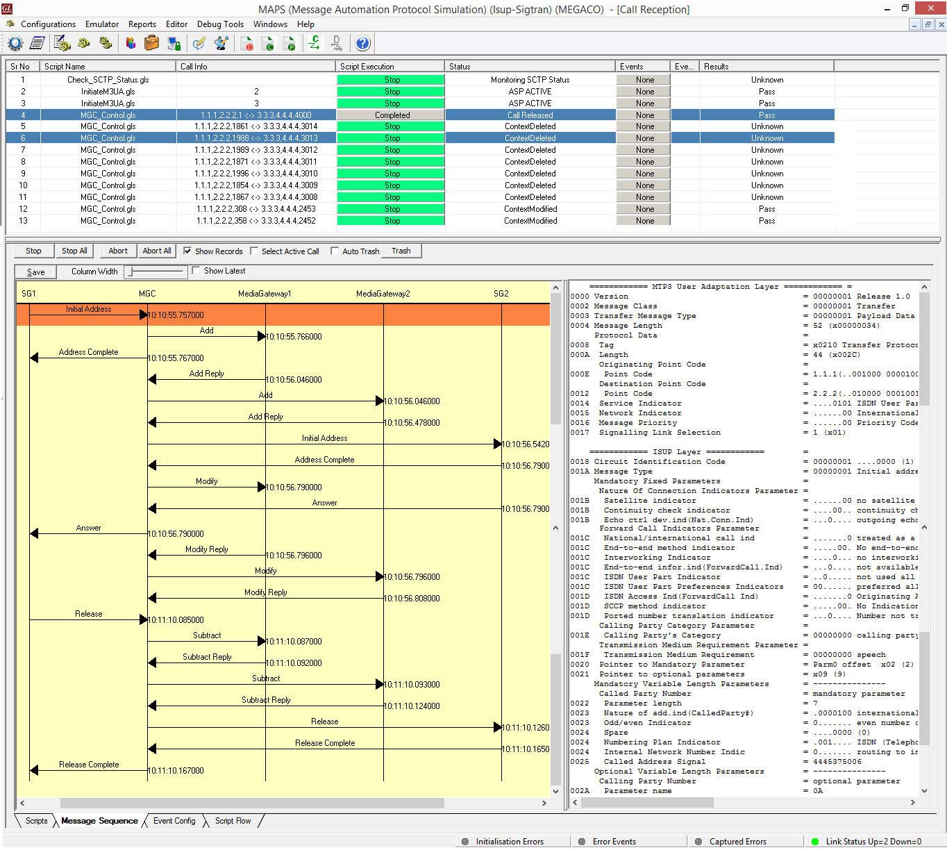
GL's MAPS™ Megaco can be configured to act as MGC, controlling singling between the SGs and handling bulk traffic between the MGs in a multi-interface Megaco network. The screenshot below depicts the SS7 Sigtran signaling flow between the SGs and Megaco procedure between MGs simulated using MAPS MGC (multi-interface).
Resources
Please Note: The XX in the Item No. refers to the hardware platform, listed at the bottom of the Buyer's Guide, which the software will be running on. Therefore, XX can either be ETA or EEA (Octal/Quad Boards), PTA or PEA (tProbe Units), XUT or XUE (Dual PCIe Express) depending upon the hardware.
| Item | Description |
| PKS122 | MAPS™ MEGACO Emulator |
| PKS123 | MAPS™ MEGACO Conformance Test Suite (Test Scripts), requires PKS122 |
| PKS102 | RTP Soft Core for RTP Traffic Generation |
| PKS300 | MAPS™ Multi-Interface MGC |
