Monitor T1/E1 Line
T1 E1 analyzer provides several ways to monitor line conditions on multiple T1/E1 lines simultaneously.
Request a Demo / Quote Brochure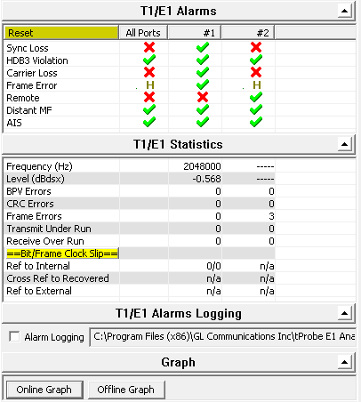
Overview
T1 E1 Analyzer provides several ways to monitor line conditions on multiple T1/E1 lines simultaneously.
A simple GUI application is used to monitor not just different types of alarms and errors, but also frequency, the power level and clock/frame/bit slips. The different types of alarms and errors monitored include - line sync loss, BPV, carrier loss, frame error, blue alarm, yellow alarm, and alarm indication signal (AIS), in case of T1 and line sync loss, HDB3 violation, carrier loss, frame error, remote, distant MF, and alarm indication signal (AIS) in case of E1.
Clock Slips are measured as a count of the difference between a reference T1 E1 clock and another T1 E1 signal being measured. A Clock Slip is a one-second-interval measurement (accuracy of the timing slips is +/- 1 count) that arise because of phases differences or frequency differences of the incoming signal vs. the outgoing signal timing (the reference).
Enough clock slips (usually counts reaching 192 or 193) create a frame slip, and eventually, lost or repeated data. GL’s T1 E1 Analyzer can measure clock slips between two T1 E1 timing signals.
GL also provides Physical Layer Analysis - a non-intrusive analysis application (requires additional license XX100) that acts like a probe to continuously monitor various alarms and error counters, and log this information to a central database over TCP/IP. The analyzer helps to track the time at which alarms (Sync Loss, Carrier Loss, Remote, Distance MF, AIS) occurred periodically and send these information to the central database over TCP/IP.
In conjunction with GL’s NetsurveyorWeb™, these non-intrusive "probes" for TDM networks deployed at strategic locations in a network, provide an instant overall graphical view of the health of the TDM network with drill down to individual lines. It provides a secure access through web, remote monitoring and diagnostics to troubleshoot any T1 E1 line.
T1/E1 Alarms Monitoring
Distant Multiframe (MF) - (E1 Only):
This indication will flash when a distant multiframe alarm is detected. A distant multiframe alarm is defined as the reception of three consecutive 1s at bit position of timeslot 16 in frame 0. This indication is only valid when in CAS mode.
Unframed All Ones - (E1 Only):
This will flash whenever an all ones condition is detected in the received bit stream. An all ones condition is defined as less than 3 zero bits received between the last align and non-align frames.
CAS Multiframe Error - (E1 Only):
This will flash whenever multiframe errors are detected that cause a resync of the frame and multiframe alignment to occur.
Remote Alarm Detected - (E1 Only):
This will flash when a remote alarm is detected. A remote alarm is defined as the reception of three consecutive 3 consecutive bits equal to 1 of timeslot 0 of non-align frames.
HDB3 Violations (E1 Only):
High Density Bipolar 3(HDB3) is a ternary transmission code in which the number of consecutive zeros which may occur is restricted to three, to ensure adequate clock recovery at the receiver. In any sequence of four consecutive binary zeros, the last zero is substituted by a mark of same polarity of the previous mark, thus breaking the Alternate Mark inversion (AMI) code. This mark termed a violation
Bipolar Violation (T1 Only):
Bipolar violations are recorded within the frame chip in an 8 bit Counter. This light will flash to RED whenever new bipolar violations are detected.
Blue Alarm (T1 Only):
This will flash when a blue alarm is detected. A blue alarm is defined as the reception of unframed all ones condition. The algorithm used is to simultaneously check for an out-of-frame (OOF) condition, and check for 14 or less zeros out of 13,895 bits. All bits, including framing bits, are tested. The alarm is cleared if OOF condition clears, or if 15 or more zeros are counted within 13,895 bits.
Yellow Alarm- (T1 Only):
This will flash when a yellow alarm is detected. The format of the alarm detected is determined by the framing format and the settings in the Config Menu. When the format for the yellow alarm is specified as bit 2 suppressed in 193S or 193E mode, a yellow alarm is defined as a "0" in bit (2nd MSB) of every DS0 timeslot for 256 or more consecutive timeslots. The alarm clears when a "1" is detected in the bit 2 position of any timeslot. If the yellow alarm is specified as FDL yellow alarm in 193E mode, then a yellow alarm is declared after 16 repetitions of "00FF" on the FDL. The alarm clears with the detection of any bit, which violates the sequence. If the yellow alarm is specified as the S-bit yellow alarm in 193S mode, then a yellow alarm is declared whenever a "1" is detected in the F-bit of frame 12. The alarm is cleared when a zero is detected in the F-bit of frame 12.
Line Sync Loss:
This will flash when a receiver resync is in progress. If the receiver is set to auto resync in the Configuration Menu the receiver will begin resync when an OOF (Out Of Frame) event or Loss of Carrier is detected.
Carrier Loss:
Carrier loss alarm is declared when 128 ± 1 consecutive zero's are detected. Carrier loss clears when a "1" is received.
Frame Error:
This will flash whenever a framing bit is in error. For T1 systems, in 193S mode, the Ft bits are monitored (odd F-bits). In 193E mode, FPS bits are monitored (F-bits of frames 4, 8, 12, 16, 20 and 24). For E1 systems, framing bit errors are detected in timeslot 0.
Alarm Indication Signal (AIS):
The receiver detects an AIS pattern when it receives less than three zeroes in any string of 2048 bits. The AIS condition is cleared when three or more zeros are detected in 2048 bits.
Features
Active:
Whenever any alarms are active, the Active indicator glows in RED informing about the alarms status.
Not Active:
The alarms are said to be not active if none of the alarms are detected on E1/T1 link. This will be show with a Green LED for the corresponding alarms.
History:
When any of the alarm is detected and then switches to not active state, the alarm is considered as History and will be shown with Yellow LED.
Error Counters, Frequency, Power Level
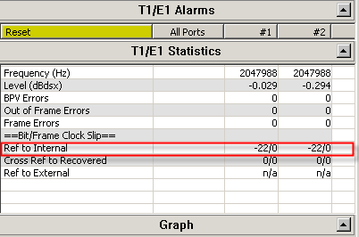
Frequency:
This shows the T1/E1 line frequency in Hertz (Hz)
Level:
This shows the T1/E1 line power in dBm
Error Counters:
BPV : This provides a counter for the BPV alarms. Uses an eight bit counter
OOF : This provides a counter for the Out of Frame alarms. Uses an eight bit counter
Frame : This provides a counter for the frame errors. Uses an eight bit counter
CRC : This provides a counter for the CRC errors. Uses an eight bit counter
Transmit Under Run :
Tx Underrun is indicative of multiframe(s) transfer problem from PC to the T1/E1 Analyzer. Whenever this error happens, T1/E1 Analyzer starves data for transmission and so previous multiframe(s) will be sent on T1/E1.
Receive Over Run :
Rx Overrun is indicative of multiframe(s) transfer problem from T1/E1 Analyzer to the PC. Whenever this error happens, PC/Application will lose multiframe(s) from the T1/E1 Analyzer.
Bit/Frame Clock Slips Functionality
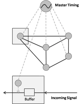
The T1 E1 hardware can measure timing differences between
- Internal Timing Source vs. Recovered Timing on Port 1, or Port 2
- External Timing Source vs. Recovered Timing on Port 1, or Port 2
- Recovered Timing on Port 1 vs. Recovered Timing on Port 2
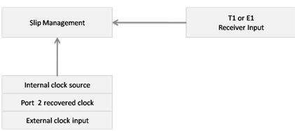
Internal Clock Slip Reference
This Clock Slip measurement compares the incoming receive clock from the port against the internal clock provided by the unit. The software compares the internal counter to the recovered clock counter by storing these counts.
Crossport Clock Slip Reference
Crossport Clock Slip Reference
This Clock Slip measurement compares the incoming receive clock from port #1 against the incoming receive clock from port #2 using the Recovered clock on port #1 and Recovered clock on port #2.
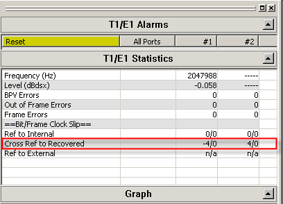
External Clock Slip Reference
This Clock Slip measurement compares the incoming receive clock using the Recovered clock of port 1 or 2 against the external clock provided on the external clock input. In this case the external clock must be either a T1 or E1 signal.
Physical Layer Analysis
Physical Layer Analysis is used to monitor T3/E3 and T1E1 line alarms. The analyzer helps to track the time at which alarms (Sync Loss, Carrier Loss, Remote, Distance MF, AIS) occurrs and periodically send these information to either centralized database such as Oracle DB, or send traps to SNMP monitoring applications.
GL’s NetSurveryorWeb™ accesses fetches the records from the central database and facilitates the user to monitor physical layer status of T1/E1 line via simple web based clients. For more details, refer to Network Line Monitor and Test
Main Features
- Captures LOS, LOF, AIS, IDLE, RAI/X-BIT, Excessive 0’s alarms at T3/E3 level.
- Captures Sync Loss, Carrier Loss, AIS, Blue, Yellow, Distance MF, Frame Error alarms at T1/E1 level.
- SNMP traps can be sent to SNMP notification receiving applications, like OpenView according to DS1-MIB (RFC 4805) and DS3-MIB (RFC 3896).
- Alarms can be captured for a specified time interval.
- Advanced filtering and search based on any user selected alarms.
- Displays Summary, Detail, Hex-Dump, and Statistics views.
- Exports Summary and Detail View information’s to an ASCII file.
- Provides options to save captured alarms into an HDL file and these files can be imported offline for further analysis.
- Channelized T3/E3 application can monitor Physical Layer Alarms up to 336 ports.
- USB T3/E3 application can monitor Physical Layer Alarms up to 12 ports.
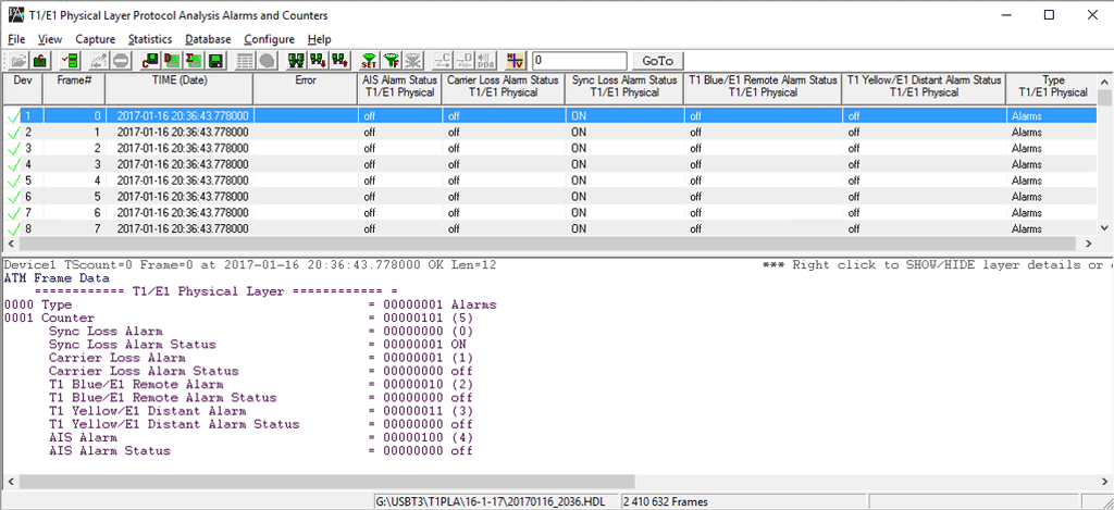
Supported T1 E1 Alarms
Line Sync Loss: This alarm indication will flash when a receiver resync is in progress. If the receiver is set to auto resync in the Configuration Menu, the receiver will begin resync when an OOF (Out Of Frame) event or Loss of Carrier is detected.
Carrier Loss: Carrier loss alarm is declared when 128 ± 1 consecutive zero's are detected. Carrier loss clears when a ‘1’ is received.
Remote Alarm Detected (E1 Only): This alarm indication will flash when a remote alarm is detected. A remote alarm is defined as the reception of three consecutive bits equal to ‘1’ of timeslot 0 of non-align frames.
Distant Multiframe (MF) (E1 Only): This alarm indication will flash when a distant multiframe alarm is detected. A distant multiframe alarm is defined as the reception of three consecutive 1s at bit position of timeslot 16 in frame 0. This indication is only valid when in CAS mode.
Alarm Indication Signal (AIS): The receiver detects an AIS pattern when it receives less than three zeroes in any string of 2048 bits. The AIS condition is cleared when three or more zeros are detected in 2048 bits.
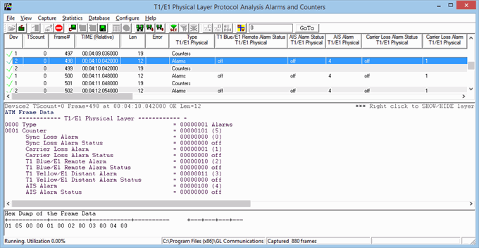
Detail View of T1 E1 Alarms
Supported T3 E3 Alarms
Loss of Signal (“LOS”) :
This is the most basic of all alarms. No signal is present. Usually this means that the cable is broken or disconnected, or that the remote device is out of service. No other alarms are meaningful when LOS is present. In the T1/E1 Analyzer, this alarm is referred to as “Carrier Loss”.
In the software Rx Framers, an all-0 signal is interpreted as Loss of Signal.
Loss of Frame Alignment (“LOFA”) : LOFA is also known as “Out-of-Frame” (“OOF”) or “Sync Loss”, a signal is present but the Rx Framer is unable to synchronize with the incoming multiframes. This usually means that either the framing strategies are incompatible (E1/T1 mismatch, DE4/ESF mismatch, etc.), or the signal is so poor that frame sync cannot be reliably established. It may also mean that the receiving equipment is expecting CRC but the sending equipment is not transmitting CRC. In the T1/E1 Analyzer, this alarm is referred to as “Sync Loss”.
Alarm Indication Signal (“AIS”) : In the T1 world, this is referred to as “Blue Alarm”. In the E1 world, it is referred to as “AIS”. The AIS/Blue Alarm signal is an unframed all-1s bit pattern. Note that a framer receiving a blue alarm will lose frame sync, and will raise a red alarm if the condition persists for more than 2.5 seconds, since the basic frame synchronization signal contains zeros.
Idle : This alarm becomes active upon reception of the T3 Idle signal. Idle alarm indicates that the line has not been provisioned for service and stays without triggering network alarms.
Remote Alarm Indication (“RAI”) : In the T1 world, this is referred to as “Yellow Alarm”. In the E1 world, it is known as “Remote Alarm Indication” or “RAI”. A device in red alarm at its receiver must transmit yellow alarm/RAI back to the sending device, alerting it that the receiving device cannot synchronize with the signal being sent. We got this one right on our T1/E1 Analyzer alarm dialogs.
Excessive 0’s : An EXZ occurrence is defined as three or more consecutive zeros in the T3 mode and four or more consecutive zeros in the E3 mode.
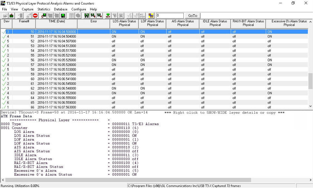
Detail View of T3 E3 Alarms
The summary view displays which alarm has occurred along with the particular timestamp and error counts. It also indicates the Frequency and Level for the counters.
Error Counters
Frequency: This shows the T1/E1 line frequency in Hertz (Hz)
Level: This shows the T1/E1 line power in dBm
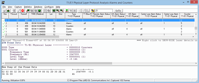
Detail View of T1 E1 Counters
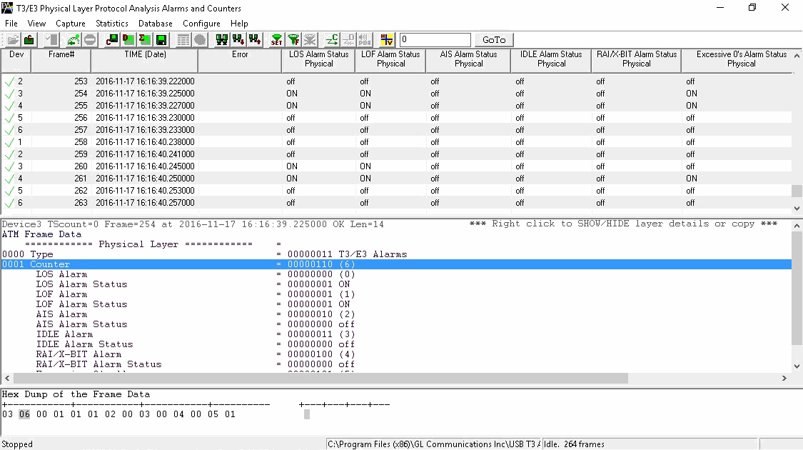
Detail View of T3 E3 Counters
Sending SNMP Traps from Physical Layer Analyzer
Physical Layer Analyzer can send SNMP traps to one or more SNMP notification receivers.
Physical Layer Analyzers continuously captures alarms on T3/E3 and T1/E1 ports. Physical Layer Analyzer sends SNMP traps when alarm status changes to SNMP monitoring applications specified by an IP Address and a UDP port.
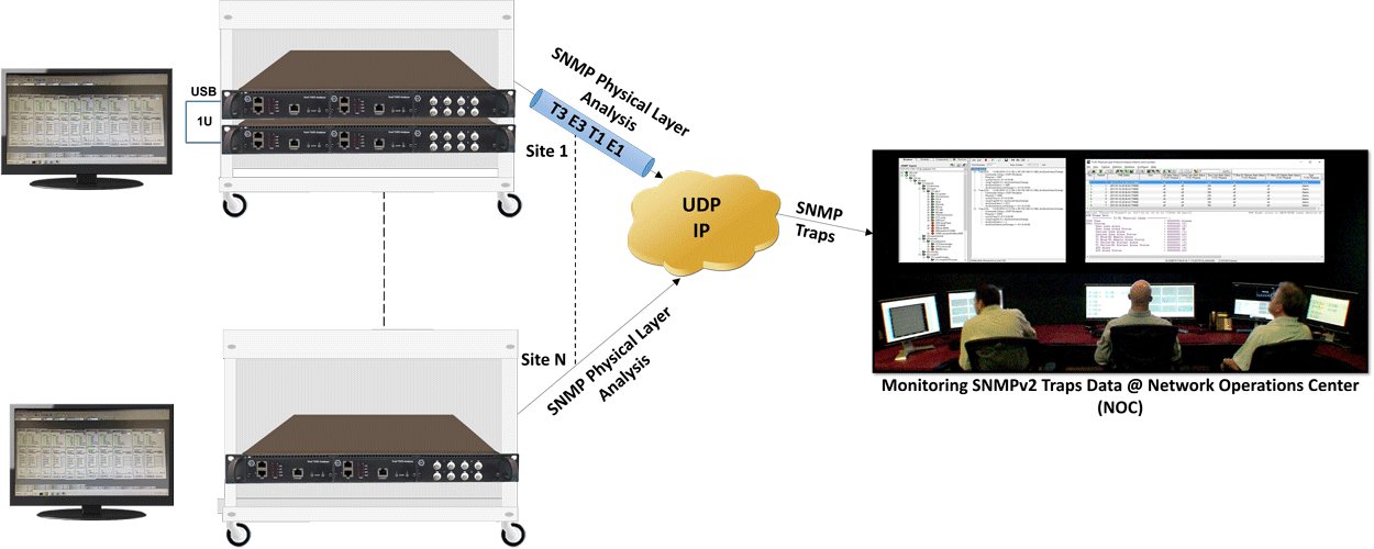
SNMP traps data are monitored at NOC using any SNMP Monitoring Application as shown below.
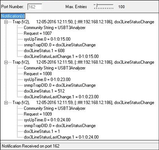
DS3 SNMPv2 Traps
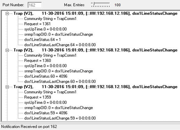
DS1 SNMPv2 Traps
Resources
Please Note: The XX in the Item No. refers to the hardware platform, listed at the bottom of the Buyer's Guide, which the software will be running on. Therefore, XX can either be ETA or EEA (Octal/Quad Boards), PTA or PEA (tProbe Units), XUT or XUE (Dual PCIe Express) depending upon the hardware.
| Item No. | Item Description |
XX100 |
Physical Layer Analysis |
|
Related Software |
|---|---|
XX629 |
|
XX648 |
|
PKV105 |
|
XX090 |
|
XX105 |
|
XX120 |
|
XX130 |
|
XX150 |
|
XX153 |
|
| Related Hardware | |
XTE001 |
Dual T1 E1 Express (PCIe) Boards (requires additional licenses) |
| FTE001 ETE001 |
QuadXpress T1E1 Main Board (Quad Port™ requires additional licenses) |
PTE001 |
tProbe™ T1 E1 Base Unit |
|
Network Monitoring Software Options |
| PKV170 | NetsurveyorWeb™ (Perpetual License, Unlimited Users/Nodes) |
| PKV169 | NetsurveyorWeb™ Lite - Probe Level WebServer, PacketScan™, and Oracle 11g Express Edition; |
PKV171 |
NetSurveyor Agent Toolkit |