Test Equipment, Solutions and Consulting for Telecom & IT
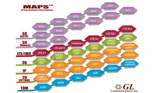
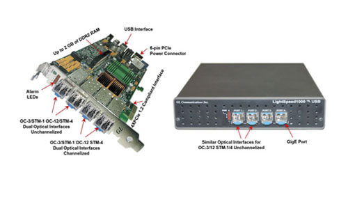
Comprehensive Testing for Analog, T1, E1, T3, E3, Ethernet, OC-3/12, STM-1/4, Wireless, and IP Networks
Comprehensive Testing for Analog, T1, E1, T3, E3, Ethernet, OC-3/12, STM-1/4, Wireless, and IP Networks