Client Server based Multi-link Frame Relay (MFR) Emulator
Frame Relay and MFR Emulation is based on client-server architecture. Acts as a Frame Relay (FR)-MFR Data Terminal Equipment (DTE)/Router and generates traffic in compliance with frame relay fragmentation & reassembly models.
Brochure Request a Demo / Quote
Overview
Frame Relay (FR) and MFR, is similar to Multi-Link PPP, and both are a form of inverse multiplexing. Users rely on inverse multiplexing when access line capacity does not scale smoothly, i.e. notice the big jumps in bandwidth from 56kbps, 1.544 Mbps, and 45 Mbps. In such cases, intermediate bandwidth must be derived by aggregating a number of smaller access lines into larger ones. MFR is used to derive a larger frame relay pipe by aggregating smaller frame relay pipes. For example, 5 T1 frame relay pipes could be bundled to appear as a single 7.5 Mbps frame relay pipe. Some of the advantages of using MFR are: better bandwidth sizing according to customer traffic requirements and potentially better QOS by minimizing delay.
MFR works by bundling multiple T1 circuits into a multilink bundle and fragmenting the individual frame relay frames into fragments. These fragments are then transported in parallel over the multiple T1 circuits. At the other end, the fragments are reassembled into the original frame relay frames. The protocol includes the use of sequence numbers to allow the fragments to be reassembled correctly and to ensure that the reconstructed frames are sent out in the original order in which they entered the network.
FR and MFR can be emulated and analyzed using GL's client-server based Multi-Link Frame Relay Emulator and Multi-Link Frame Relay Analysis software modules. These are available as optional applications with GL’s T1 E1 Analysis hardware platforms such as tProbe™ T1 E1 Analyzer, Dual T1 E1 PCIe Express Cards, and Quad/Octal T1 E1 Analyzer.
Multi-Link Frame Relay Emulator can be configured as a router or as a bridge to establish connection and route traffic between LANs. The application may be accessed through a GUI or through command line scripts.
Main Features
- Performs MFR as well as FR simulation on up to 16 T1 E1 lines
- Adheres to FRF.12 standards
- Support two simulation modes - FR and MFR
- FR links can be created on Full or Fractional Timeslots
- Group FR links to create a MFR bundle
- Dynamically add/remove (open/close) of Frame Relay links without loss in data
- Multiple MFR Bundles/FR links can be created with each bundle/link configured with multiple virtual channels for traffic Tx/Rx
- Generate and verify end to end traffic on each Virtual Channel
- Transmit and receive Ethernet traffic over T1 E1 links by operating either in bridge or router mode
- User configurable FR/MFR packet and fragment size, bandwidth using flags, and maximum link differential delay
- Supports Layer 2, Layer 3 and Layer 4 Bert packets to send out via Route table
- Supports both Interface (UNI and NNI) and End-to-End fragmentation
- Payload traffic generation and verification using Sequence number, pre-captured HDL files (containing packets/frames), Flat Binary file, and User defined frame (ASCII HEX file) for each Virtual Channel independently
- Supports various traffic source/sink types namely, Sequence Number, Binary File, Hex String, and pre-captured HDL files
- Supports various Byte level, Frame level , CRC error, and Frame error impairments at link level
- Supports various Byte level and Frame level impairments at Fragment/Packet level for each Virtual Channel
- Provides detailed statistics for each bundle and virtual channels associated with a bundle
- Ability to record the Frame Relay (FR) traffic.
- Provides end to end traffic verification statistics
- Ideal solution for automated testing using command line scripts
Simulating Frame Relay links
Various links (of any bandwidth varying from 64Kbps to n*64Kpbs or sub channels) can be added in FR Simulation .Two or more than two timeslots can be grouped to constitute a Hyper-channel.
Each of the added links can be configured with Fragmentation size, Flags between HDLC Frames, and Impairments.
Links in FR Simulation
Link Configuration
This feature provides Frame Fragmentation configuration adhering to FRF.12 standard for traffic generation on selected FR links. The application supports two types of fragmentation: UNI NNI Fragmentation and End-to-End Fragmentation on a FR link. If fragmentation configuration is not enabled then the generated FR traffic will have 2 byte frame relay header only. The application also allows to configure the bandwidth using flags.
Link Config Layer
Simulating MFR Bundle
MFR bundles multiple link-layer channels into a single network-layer channel. The MFR Simulation allows to create a virtual interface referred as 'bundle' interface. An MFR bundle can consist of multiple physical links of the same type or physical links of different types. Data sent through this channel will be distributed among all the links. MFR bundles technique is used to derive larger bandwidth pipe by aggregating smaller bandwidth pipes e.g. from multiple T1s or E1s.
MFR Bundles and Links
Bundle Configuration and Statistics
Similar to a link, Fragmentation Size and Maximum Differential Delay can be configured for a selected bundle in the Bundle Config screen. Bundle Statistics will show statistics of transmitted frames, received frames, transmitted octets, and received octets for a selected bundle.
Bundle Config & Statistics
Impairments
Impairments enable the user to intentionally introduce errors in data transmission. Impairments can be applied at different levels, i.e.
- Impair all packets sent over a Physical Link
- Impair frames on a particular Virtual Channel [VC may be on a physical link or on the MFR bundle]
- Impair frames on a particular Aggregated Virtual Channel
- Impair all packets on the MFR bundle
Impairments can be applied to a link either before data transmission or during the process of data transmission. Different kinds of impairments are available to perform the task. Bytes can be modified through Delete bytes, Insert bytes, and AND/OR/XOR options. An entire FR frame can also be impaired through Delete, Insert, Duplicate, CRC errors, and Frame errors. Following impairment types are supported:
- DELETE - Delete few bytes in a frame or the delete the full frame itself
- INSERT- Insert few bytes in a frame or insert the full frame itself
- DUPLICATE - Duplicate a frame given number of times
- AND, OR, XOR - Logically And/Or/Xor an octet in the frame
- CRC - Introduce CRC error
- FRAME ERROR - Introduce frame error
- DELAY - Delay transmission on a physical link by x msec
- ABORT - Allows users to send the Abort flag over the line
For selected links, differential delay can be introduced between links. The delayed links in the links can also be brought back to sync with the Synchronize option.
Impairment Types
Pattern/File Traffic
The source of the traffic is either a file or a repetitive pattern as defined by the user. This traffic type can be used for end-to-end testing of the link. Since fixed known traffic pattern is generated, the receiver side can be configured to verify the received traffic against the same fixed pattern.
The verification process will provide results such as how many frames are received and out of which how many have been matched successfully with configured pattern, similarly, how many frames modified etc.
BERT test can also be conducted using various pre-defined patterns or a user defined pattern file. The BERT verification provides statistics like: Bit Errors, Sync Loss Count, Sync Status etc.
A virtual channel is created for selected links or bundle to perform traffic actions. In FR simulation the VC will be created on the selected link from the 'Links' dropdown menu. In case of MFR simulation VC will be created on the selected bundle. Multiple Virtual Channels (VC) can be created on the same physical link with same fragmentation format and fragment size.
Tx parameters will generate the FR traffic. Received data is verified with respect to the selected Rx parameters and results of verification are available in Tx/Rx verification tab. The parameters for each VC are independently set. The Tx/Rx parameter includes:
- Data Type (Sequence No, Packets from HDL or BIN files, HEX string, or Network Traffic). Network traffic allows users to receive traffic from Ethernet LAN, convert to FR traffic and send through T1 E1 line and vice versa. MFR emulator can be configured to work as router or bridge to establish connection between two systems residing in two different LANs.
- Data Type Parameters
- Prefix Header
- Duration Specification
- Payload length
- Impairments
FR - VCs on a Selected Link
MFR - VCs on a Selected Bundle
TxRx Verification
The results of the verification for each of the added VCs are available in Tx/Rx Verification. The statistics include:
- The number of VCs created
- The number of frames transmitted successfully
- The number of frames received successfully
- If a received frame is verified successfully, then it will be included in "Matched" Frame Count
- If a received frame does not match, it will be included in the "Modified" Frame Count
- If the frame is lost then it will be included in "Deleted" Frame Count
- If extra frames have been received which were not expected then they will be included in Inserted Frame Count
Tx/Rx Verification for Each VC
MFR Emulator as a Router
The MFR Emulator allows user to setup routing table by configuring IP Address and Mask. Once configured, the emulator forwards the IP packets which match routing criteria over MFR links. The emulator responds to all ARP requests whose IP addresses present in routing table. Shown above, are two networks, Subnet1 and Subnet2, connected through T1 E1 lines using MFR Emulator that is configured to work as router.
MFR Emulator as a Bridge
When the MFR Emulator is configured to act as bridge between two networks, all ARP and traffic received from the network is encapsulated as bridged IP and streamed over T1 E1 links. The Emulator on another network removes bridging header, converts to Ethernet and streams to the destination.
PacketCheck Traffic
MFR-IP-PacketCheck traffic option allows IP traffic generation and reception over FR links. Multiple IP traffic streams can be generated and processed over multiple VCs created within the FR links. Each IP traffic streams can be configured to modify the IP packets with desired custom headers to emulate various protocols. MFR-IP-PacketCheck traffic is used to generate and receive IP packet streams to and from a FR router. The FR Router shall be tested for routing the received packets to the proper destination. Using GL's IP tools like PacketCheck™ and PacketExpert™, one can conduct end-to-end testing of the FR link through the FR router.
PacketCheck Traffic Configuration
Route Configuration
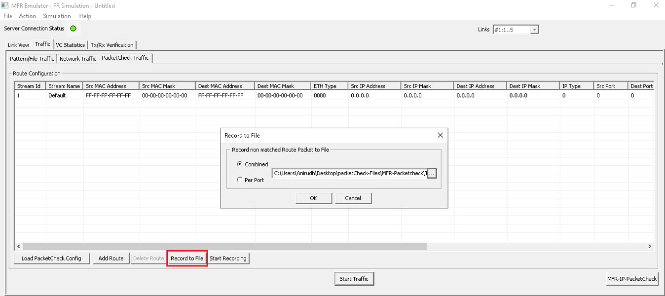
PacketCheck™ Traffic Recording
In PacketCheck™ Traffic, frames that do not match any configured parameters in the Route table, as well as errored frames will be recorded. Can record the traffic in HDL file formats, which can then be conveniently analyzed using Wireshark® or the PacketScan™ applications.
PacketCheck™ Traffic Recording
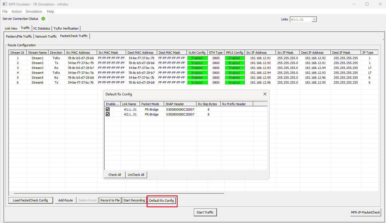
Default Rx Configuration
The traffic arriving on T1/E1 Frame Relay links that does not match predefined routing rules is typically discarded. With Default Rx routing, this traffic can be automatically forwarded to PacketCheck™, ensuring unmatched packets are still captured, analyzed, and verified.
Default Rx Configuration
Link Statistics
Provides important statistics information for the selected link such as such as the Number of frames transmitted, Received frames, Octets Transmitted, and Octets Received.
Statistic Layer
VC Statistics
The statistics for each of the added VCs are available and these include number of Transmitted and received frames, Fragments, Octets, and Lost fragments.
Tx/Rx Statistics for Each VC
HDLC Statistics
Errors that occur during transmission / reception like the Tx Under/Over Runs, Rx Under/Over Runs, number of FR packets with bad FCS, and number of packets with Frame Errors is recorded in the HDLC Statistics fields.
HDLC Statistics Layer
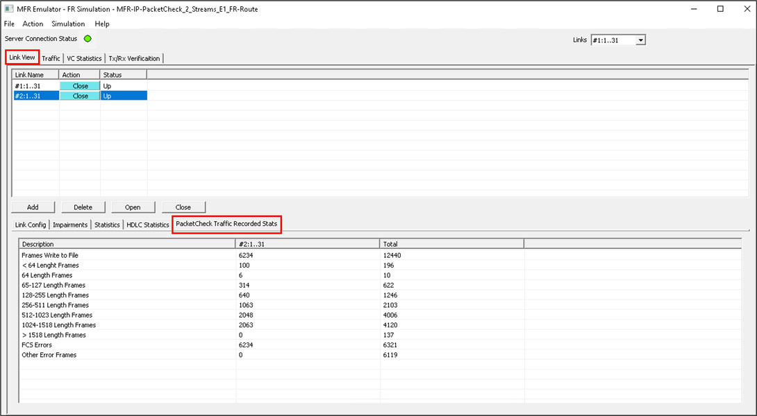
PacketCheck™ Traffic Recorded Statistics
The PacketCheck™ Traffic Recorded Statistics tab displays the recorded frame count, errored frame count for the selected links, and the total count for all configured links.
MFR Emulation using Command Line Interface (CLI)
Adding and Activating Frame Relay links (streams)
Syntax: inform task n "TS [HC|SC] 'Link Name'";
Syntax: inform task n "ACTIVATE TS [HC|SC] 'Link Name'";
It is used to add new frame relay links (streams) to the task. In FR simulation the added links are independent of each other, and Virtual Channels will be created on each individual link. In MFR simulation all the added links will constitute one MFR bundle, and Virtual Channels will be created on the bundle but not the constituent bundle links.
The activate command is used to activate /deactivate the individual bundle links in the MFR bundle. Provides an option to dynamically activate/deactivate the links, deactivated links are not be used for Tx/Rx.
MFR Simulation in CLI
Creating/deleting Virtual Channels on the links
FR simulation:
Syntax: inform task n "CREATE VC HC #1:0..23 DLCI x FRAG FORMAT UNI NNI [END TO END] FRAGSIZE n";
MFR simulation:
Syntax: inform task n "CREATE VC DLCI x [y z ...] FRAGSIZE n";
This is used to create or delete virtual channels on the FR links. In case of MFR simulation, virtual channels are created on the MFR bundle.
Traffic Generation and Verification
FR Simulation
Syntax: inform task n "Tx[Rx]: HC #1:0..23 DLCI x CONT [FRAMES n |EOF] FIXLEN 1500 SEQNUM MSB4 [MSB|LSB 8|2|1]";
MFR Simulation:
Syntax: inform task n "Rx:[Tx:] DLCI x CONT FIXLEN 1500 SEQNUM MSB4";
Aggregated Virtual Channel
Syntax: inform task n "Rx [t]: HC #1:0..23 AVC x CONT [FRAMES n|EOF] FIXLEN 1500 SEQNUM MSB4 [MSB|LSB 8|2|1]";
In MFR Simulation the traffic is generated and received on the entire MFR bundle. But in FR simulation, traffic can be generated and received on each individual FR link. Transmission parameters are used to generate traffic and receiving parameters are used as reference to verify the received frames.
Applying Impairments on Frame transmission
Syntax: inform task n "ERROR REP n [CONT] SKIP m #1:0..23 DLCI x OFFS x DEL x";
To download the Multi-link Frame Relay Client-Server T1 E1 scripts.
Resources
Note: PCs which include GL hardware/software require Intel or AMD processors for compliance.
Please Note: The XX in the Item No. refers to the hardware platform, listed at the bottom of the Buyer's Guide, which the software will be running on. Therefore, XX can either be ETA or EEA (Octal/Quad Boards), PTA or PEA (tProbe Units), XUT or XUE (Dual PCIe Express) depending upon the hardware.
| Brochures |
|---|
| T1 E1 Client Server Multi Link Frame Relay Emulator Brochure |
| Presentations |
|---|
| MFR Emulator Presentation |