T1 E1 Transmit Tone / Gaussian Noise Multiframe / Signaling Bits
Transmit Tone, Transmit Gaussian Noise, Transmit Multiframe, Transmit Signaling Bits application is included with T1 E1 Basic Software
Transmit Tone
Transmit tone application allows you to transmit a tone of any frequency (within 5 Hz to 4000 Hz) into one or more timeslots simultaneously (the frequency and power level of the tone are adjustable). In addition, this application provides a frequency sweep feature wherein the tone frequency is automatically stepped through the frequency range.
In addition, you can set the values of the A, B, C, and D signaling bits (A and B only if the T1 card is in 193S (D4) framing mode).
To transmit different frequency tones into different timeslots, invoke this application multiple times.
For T1 systems, transmitting a tone into all timeslots may cause a "yellow alarm". This is because a yellow alarm is defined as 250 consecutive zeros in the next to most significant bit of all timeslots. To avoid this condition, send a tone into not more than 23 timeslots or send different tones into different timeslots by invoking multiple instances of the application.
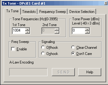
Tone Frequencies (in Hz)
This setting allows single tones from 5 Hz to 3995 Hz to be transmitted on
selected channels.
Tone Power (in dBm)
This setting allows tone power to be set in the range from -40dBm to 3dBm.
Signaling
- OFF-Hook -- The Analyzer's current Off Hook signaling bits pattern is applied to the outgoing T1/E1 data stream.
- ON-Hook -- The Analyzer's current On Hook signaling bits pattern is applied to the outgoing T1/E1 data stream.
- Clear-channel - "Clear channel" forces the applicable timeslot into the clear-channel condition regardless of any previous commands from any other clients or task threads, which simply states that a process has no interest in the signaling bits being transmitted.
- Don't Care -- Indicates that a script / application has no interest in the signaling bits being transmitted on the applicable timeslot. Thus if some other script has previously specified a signaling bits control action, that action will be reinstated. Observe random variation of signaling bits for T1 and Idle code (D5) for E1 in monitor signaling bits window.
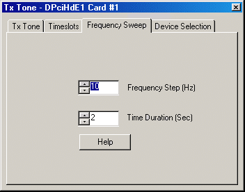
Frequency Sweep
User can select the time duration and the frequency value for the frequency sweep.
When frequency sweep is enabled, the frequency of the tone selected will change in steps according to the 'Frequency Steps'
and 'Time Duration' specified as shown in the screenshot below:
Timeslots
Allows user to select the channels on which the tone is to be transmitted.
Device Selection
Allows user to select the card on which the tone is to be transmitted.
Example
Cross-connect port1 and port2 of T1/E1 cards and continue with the following process:
- Step 1:
Transmit a tone into Timeslot 1 at a Frequency of 1004 Hz on card1. Then verify that the tone is being sent as follows:
- Hear the tone through the speaker on card2 timeslot 1.
- Confirm that the values in "byte values" window are changing on the appropriate timeslot on card2.
- Observe on the spectral page, the oscilloscope page, the frequency box, power box, and signaling box on card2 timeslot 1 for appropriate changes.
- Enable the 'Frequency Sweep' and set Time Duration to say 5 seconds and Frequency Step to say 1000 Hz. Now observe in the oscilloscope that for every 5 seconds time duration there will be shift in tone frequency by 1000Hz.
Step 2:
- Step 2A: Control Signaling Bit Transmission with Tx Tone (or Tx Gaussian Noise) Application:
To illustrate this the following steps have to performed,
- Invoke Monitor Signaling Bits on Card #2, note the received pattern. It may be 1111 for T1 systems if Card #1 is
transmitting idle code. For E1 systems, you may see 1101 in the lower 15 timeslots and 0101 in the upper 15 timeslots, corresponding
to idle code D5 hex.
- Invoke Transmit Signaling Bits on Card #1, select all timeslots, and then choose a distinctive pattern such as "1100". Note that the pattern now appears at Card #2. Deselect timeslot 1 and press "Transmit". Note that the signaling bits received at Card #2 timeslot 1 revert to their previous pattern. This is because Transmit Signaling Bits relinquished control of timeslot 1. No other application had requested signaling bits control of that timeslot, so the system disabled signaling bits transmission. This mode is referred to as "Clear-channel" mode, where the data bits appear in the signaling bits positions.
- Invoke Monitor Signaling Bits on Card #2, note the received pattern. It may be 1111 for T1 systems if Card #1 is
transmitting idle code. For E1 systems, you may see 1101 in the lower 15 timeslots and 0101 in the upper 15 timeslots, corresponding
to idle code D5 hex.
- Step 2B: Tx Tone/Tx Gaussian Noise
Timeslot1 is set free by Tx signaling bits application on card#1, however other timeslots will have the signaling bits being transmitted as set by Tx signaling bits application.
Now lets use Tx Tones on other timeslots from 1 to 11 to Tx tones (or use Tx Gaussian Noise application to transmit noise from 1 to 11). Select Card #1 and timeslots 1 through 11.
- DON'T Care Mode: Select "Don't Care" signaling and press "Start". Signaling bits for all timeslots other than
timeslot 1 remain unchanged. The timeslot1 instead shows randomly generated data bits in T1 systems, while in E1 systems; timeslot
1's signaling bits show the upper nibble of the idle code.
- CLEAR CHANNEL Mode: Now select "Clear Channel" signaling. On T1 systems, timeslots 1 through 11 now
all show a varying pattern of signaling bits at Card #2. Thus the signaling bits positions carry random data bits. On E1 systems,
timeslots 1 through 11 all carry the pattern due to the upper nibble of the idle code.
- OFFHOOK & ONHOOK Mode: Now select "OFF-Hook" signaling in the Tx Tone application. Card #2 shows the
OFF-HOOK signaling bits pattern in timeslots 1 through 11. Now click on the Transmit Signaling Bits application and select another
distinctive pattern such as 0011. Note that Card #2 now shows all timeslots except timeslot 1 carrying the new signaling bits pattern.
Timeslot 1 still shows the Off Hook pattern, which is still controlled by Transmit Tone application. The same is followed for "ON-HOOK"
mode.
- Rx Signaling Mode (applicable to Tx Gaussian Noise only): Reactivate Transmit Gaussian Noise and select "Rx Signaling". Note on Card #2 that the signaling bits on timeslots 1 though 11 are the default signaling bits from Card #2 that arises from the idle code. That is, no signaling bits control has been specified for Card #2, nor has any application inserted data on its timeslots. Therefore, all Card #2 Tx time slots are in clear-channel mode and are transmitting idle code. Therefore, the signaling bits reported by Monitor Signaling Bits are simply those due to the idle code being transmitted from Card #2 and relayed through Transmit Gaussian Noise. The pattern is normally 1111 for T1 systems and 1101 (the upper nibble of D5 hex) on E1 systems. All other timeslots continue to show the 0011 being transmitted by Transmit Signaling Bits.
- DON'T Care Mode: Select "Don't Care" signaling and press "Start". Signaling bits for all timeslots other than
timeslot 1 remain unchanged. The timeslot1 instead shows randomly generated data bits in T1 systems, while in E1 systems; timeslot
1's signaling bits show the upper nibble of the idle code.
- Step 2A: Control Signaling Bit Transmission with Tx Tone (or Tx Gaussian Noise) Application:
Transmit Gaussian Noise
Transmit Gaussian Noise application allows you to transmit Gaussian Noise into one or more timeslots simultaneously (the power level of the noise is adjustable from -140 dBm and up to a maximum of +3.17 dBm). Gaussian noise is characterized by having random signal values whose amplitude values follow a Gaussian distribution. The transmitted Gaussian Noise can be viewed in the Spectral Display and the Power Level window.
All selected time slots in a given Gaussian Noise window will have identical noise signals. To transmit different noise signals or noise at different power levels into different timeslots, invoke multiple instances of this application.
- Timeslots Selection:
Click the timeslots on which the noise has to be generated at the specified power level. Note that, in E1 systems, timeslot 0 is never available. Also, the time slot 16 is available only when the selected T1 E1 card is in CCS signaling mode.
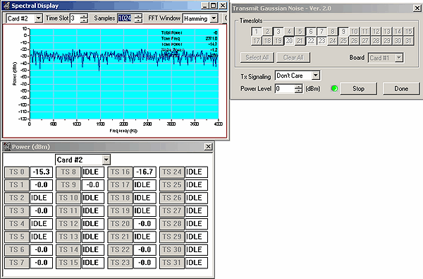
Generate:
Click Generate to transmits the noise with the specified power level on a continuous basis. When the Generate button is pressed, its label changes to "Stop", and the green LED indicator flashes to indicate that noise is being inserted onto the selected time slots.
Stop:
Click Stop to end the transmission of the Gaussian Noise signal. This inserts idle on all selected time slots. The button label is changed back to "Generate", and the green LED indicator is switched off.
Select All:
Click Select All to select all the timeslots to transmit Gaussian Noise.
- Clear All:
Click Clear All to deselects all the timeslots. - Done:
Click Done to terminate the application. - Board:
Select a card from the Board dropdown list to insert the Gaussian Noise on that card. - Power Level:
Set the power level here. Valid selections are in the range of -140 dBm to +3.17 dBm for T1/U-Law systems and for E1/A-Law systems. - Tx Signaling:
The various signaling bits options are
- Don't Care - Indicates that a script / application have no interest in the signaling bits being transmitted on the applicable timeslot. Thus if some other script has previously specified a signaling bits control action, that action will be reinstated.
- Clear-channel - "Clear channel" forces the applicable timeslot into the clear-channel condition regardless of any previous commands from any other clients or task threads, which simply states that a process has no interest in the signaling bits being transmitted.
- Rx Signaling - The signaling bits arriving at the T1/E1 Input of the Receive Path card are copied to the corresponding timeslots of that card's T1/E1 Output. In other words, the incoming signaling bits are 'preserved'.
- OFF-Hook - The Analyzer's current Off Hook signaling bits pattern is applied to the outgoing T1/E1 data stream.
- ON-Hook - The Analyzer's current On Hook signaling bits pattern is applied to the outgoing T1/E1 data stream.
Example
- Cross-connect port1 and port2 of T1/E1 cards and invoke the "Transmit Gaussian Noise" application on card2. Select timeslot 1 and press generate. Hear the noise on the speaker of timeslot1. Similarly, observe the noise on Spectral Display and the Oscilloscope Display on card1, timeslot 1. One can also observe the power level on the Power level window on card1, timeslot 1. Repeat the above steps on all the time slots and verify the same.
- Follow step2 as explained in Tx Tone application, for control signaling bit transmission with Tx Gaussian application.
- Follow step3 as explained in Tx Tone application for various signaling modes available.
Transmit MultiFrame
The user can define the contents of a multiframe for repeated transmission. Data may be entered directly into the array with the help of cursor and keyboard. For E1 Cards the hardware overwrites timeslot 0. Timeslot 16 is overwritten in the first frame of a multiframe when the E1 format is in Channel Associated Signaling (CAS) mode. In Common Channel Signaling (CCS) mode, timeslot 16 is transmitted as defined in the multiframe buffer.
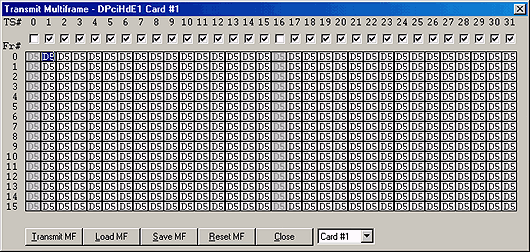
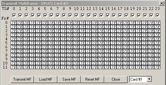
- Transmit MF:
Click Transmit MF to transmits the defined multiframe on a continuous basis. - Load MF:
Click Load MF to load a predefined multiframe from the disk. - Save MF:
Click Save MF to save the defined multiframe onto disk with a user specified filename. Reset MF:
Click Reset MF to permit easy defining of the multiframe on the specified timeslots.
- Close:
Click Close to terminate the application.

Example
Cross-connect port1 and port2 T1/E1 cards and invoke the "Byte Values" window from the monitor
menu on card2 Invoke the "Transmit Multiframe" application on card1 and click 'Reset MF'. Modify the multiframe by transmitting a
value such as 06 on all timeslots and click 'Transmit MF'. Observe the modified multiframe on the byte values application.
Transmit Signaling Bits
Transmit Signaling Bits application allows you to transmit the signaling bits into one or more timeslots simultaneously. The transmitted Signaling Bits can be viewed in the Signaling Bits and Signaling Transitions application.
- Transmit:
Click Transmit to transmit the specified Signaling Bits into the specified timeslots. - Close:
Click Close to terminate the application. - Select All:
Click Select All to select all the timeslots to transmit Signaling Bits. - Deselect All:
Click Deselect All to deselect all the timeslots. - Save:
Click Save to save the configuration. - Load:
Click Load to load the previously saved configuration.
Example
Cross-connect port1 and port2 of T1/E1 cards and invoke the "Signaling Bits" application
on both the cards. Also invoke the "Transmit Signaling Bits" application on both the cards.
Modify the signaling bits in
Transmit Signaling Bits as follows:
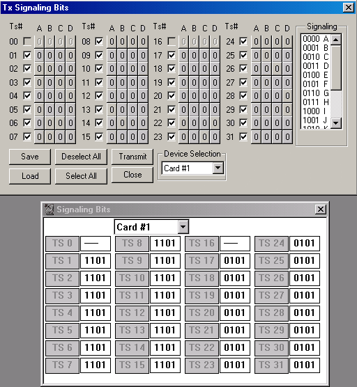
- Select 0000 as signaling pattern and check all the timeslots to transmit on all channels. Observe that all the signaling bits are immediately changed on Signaling Bits application to 0000. Now select 0010 as signaling pattern and select only one timeslot box (say TS 1). Observe that signaling bits are changed on Signaling Bits TS 1window.
- To transmit different signaling patterns on different timeslots, click to change the individual ABCD signaling bits value associated with each timeslot. Observe that the same signaling bits in the view box are reflected.
 Back to List of T1E1 Basic and Optional Applications Index Page