GL Announces Interconnect User Part (IUP) Protocol Simulation
Welcome to a September 2014 issue of GL's Newsletter providing information and insight into our latest product - simulation of UK specific SS7 Interconnect User Part (IUP) Protocol over TDM network, referred to as MAPS™ IUP Protocol Simulator.
Overview
The SS7 (C7) IUP is UK national standard protocol used to interconnect two Public Network Operators. The IUP feature was derived from the standards of the Public Network Operators - Interconnect Signaling Committee (PNO-ISC).
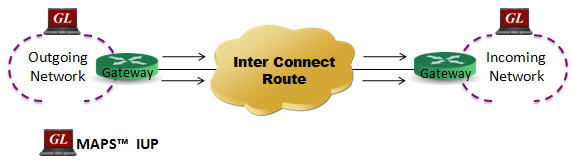
GL's MAPS™ IUP is an advanced protocol simulator used to simulate UK specific SS7 IUP protocol in British Telecom (BT) networks. It is designed to simulate interconnect route between incoming and outgoing networks as defined by theTGS/SPEC/006 and PNO-ISC/INFO/004 specifications. MAPS™ IUP functionality covers the UK variant of SS7 implementing MTP2, MTP3 protocol standards TDM (T1/E1) transport layer. Ready scripts are available supporting various protocol services including Basic Call Service protocol (IFAM, IAM, ACI, Bearer Establishment), Request Service protocol, Nodal End-to-End Data protocol, Enveloped ISUP Essential Service protocol, and ISDN Call Handling Service protocol.
Listed below are the supported IUP procedures by MAPS™ IUP -
- Bearer establishment
- IFAM Protocol
- IAM (SND) Protocol
- IAM (SAD) Protocol
- Subsequent Address Message (SAM)
- Final Address Message (FAM)
- Call Establishment
- IUP Basic Call Service: (Service Handling Protocol)
- Request Service Protocol (Service Handling Protocol 2)
- SASUI Protocol (Supplementary Call Information)
- ACI Protocol (Supplementary Call Information)
- Nodal End-to-End Data Protocol (Service Handling Protocol 3)
- ISDN Call Protocol (Service Handling Protocol 1)
- Enveloped ISUP Essential (Service Handling Protocol 8)
- Call Supervision
- Connection not completed - SUBSCRIBER ENGAGED or SUBSCRIBER OUT
- Call Release
- Connection not completed - CNA procedures
- Connection not completed - RELEASE procedures
- Bearer Release Protocols
Supported Protocol Standards
IUP Protocol Stack
| Supported Protocols | Standard / Specification Used |
|---|---|
| IUP | ND1006:2007/05 TSG/SPEC/006 (IUP) ND1104:2004/11 PNO-ISC/INFO/004 (Proprietary Extensions to IUP) ND1301:2001/03 DPNSS (Digital Private Signaling System No 1 (DPNSS 1) ) ISDN User Part (ISUP) UK - ND1007:2001/07 PNO-ISC/SPEC/007 |
| MTP3 UK | ITU-T Recommendation Q.703 |
| MTP2 UK | T-REC-Q.703-199607 |
Main Features
- IUP simulation over TDM (T1/E1)
- Multiple T1/E1 line interfaces supported
- Supported procedures - Basic Call Service protocol (IFAM, IAM, ACI, Bearer Establishment), Request Service protocol, Nodal End-to-End Data protocol, Enveloped ISUP Essential Service protocol, and ISDN Call Handling Service protocol
- User-friendly GUI for configuring the SS7 MTP Layers
- User-configurable Signaling Links
- User-configurable Circuit Mapping - Define Circuit Identification Codes (CIC) and map these CICs to Timeslots/Trunks in order to enable Voice/Data traffic
- Supports MTP2 and MTP3 protocol machine
- Multiple MTP links
- Supports client-server functionality through Command Line Interface (CLI) such as the Python, and TCL (requires additional license)
- Supports scripted call generation and automated call reception
- Provides protocol trace with full message decoding, and graphical ladder diagrams of call flow with time stamp
- Provides call statistics with associated captured events and error events during call simulation
Typical Call Procedure
Shown below is the typical call procedure in IUP interfaces:
Basic (Telephony) Service Handling Procedure
Call Generation
IUP Basic (Telephony) Call Generation
Call Generation option allows the user to simulate outgoing communications where an outgoing call is initiated by sending call control messages using proper scripts and profiles. The profile allows necessary parameters of call control messages to be changed during runtime.
The screenshot below shows MAPS™ IUP acting as Outgoing Network and initiating the procedure by sending the IUP IAM (Initial Address Message) to the incoming network, establishing an end to end connection between incoming and outgoing networks suitable for telephony calls.
Call Reception
IUP Basic (Telephony) Call Reception
Call generated from other entity can be automatically detected in call reception window by pre-setting the required scripts in the Incoming Call Handler window.
The screenshot below shows MAPS™ IUP configured to act as Incoming Network terminal, which receives and responds to the incoming messages.
Bulk Call Simulation for Load Testing
MAPS™ supports Bulk Call Simulation and Stress/Load Testing capabilities through Load Generation feature. Load Generation can be customized with different statistical distribution patterns such as Uniform, Ramp, Sawtooth, Fixed, Normal, Step, and Step-Sawtooth distribution. Call duration also can be randomized using similar statistical distribution. Load Generation window helps users configure Stress/Load Testing parameters such as Call per second (CPS), Max Active Call, Minimum and Maximum Call Rates, Start Call Rates, and other parameters.
To simulate protocol and traffic behavior, respective test scripts can be loaded along with the associated number of profiles, which provide input parameters during script execution.
Call Statistics
Call Status & Message Statistics - By default, all call handling scripts (irrespective of the type of the functions) are assessed by MAPS™ to provide statistical information about Total Calls, Active Calls, Completed Calls, Passed Calls, Failed Calls, and Calls/Sec. It is also possible to categorize the statistical information as per the call handling scripts.
In addition, Message Stats option for any specific protocol, logs number of times the messages are being transmitted (Tx Count) and received (Rx Count), thus allowing user to monitor the occurring events.
 Back to Newsletter Index Page