PRI ISDN Protocol Emulator
Overview
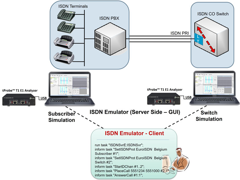
GL's ISDN Emulator offers a complete solution for testing, troubleshooting, installation and maintenance of devices and networks implementing PRI ISDN. It is useful to test ISDN products designed for either U or S/T interface, including network terminations, Type 1 terminating equipment, and terminal adapters. ISDN equipment includes telephones, switchboards, PBXs, PC cards, Video Conferencing Equipment, Interconnect Systems, switches and routers.
GL's ISDN Emulator for T1 E1 network is available as GUI based as well as Command-line based applications through which the various ISDN configurations can easily be created, thereby allowing the ISDN Emulator to be fully functional within a few minutes. This ISDN configuration includes selection of various ISDN standards, variants & NFAS, etc. The ISDN Emulator also incorporates the flexibility to modify ISDN call parameters & message content. This flexibility ensures that the ISDN emulator will communicate with the system under test. It's even possible to emulate a complete ISDN connection (switch to subscriber) all in the same PC with a dual interface card.
For more information, visit client-server based ISDN Emulation webpage.
Main Features
- Nearly all ISDN standards and variants are supported. Variants for T1 analyzers include AT & T #4ESS, AT & T #5ESS, Bellcore #5ESS, National ISDN 2, Nortel, DMS - 250, and Siemens EWSD, while for E1, Variants are Belgium, China, Europe, France, Britain, Germany, and Sweden
- 1 to 4 Configurable Signaling Links.
- Supported protocol layers - LAPD and Q.931 Layers
- Switch and Subscriber Emulation
- User Friendly GUI for Configuring the ISDN Layer parameters. Includes configuring for Called/Calling Numbering Plan/Type, type of ISDN service, etc. These ISDN parameters may be saved within a Timeslot group so as to allow multiple ISDN parameter configurations, simultaneously.
- Quick configuration for Called & Calling Number
- Provides various release cause codes such as rejected, no user response, user busy, congested, and so on to troubleshoot the problems in ISDN
- Simple NFAS setup for T1
- Single/Dual T1, Single/Dual E1 Interfaces for the ISDN Signaling Links.
- Call Records for Complete or Incomplete Calls
- Companion product "ISDN Protocol Analyzer" displays all ISDN Messages in Real Time.
- Place call or accept call for each timeslot or for the whole trunk.
- Supports Overlap Digit Sending
- Exports call records to a TEXT file.
- Displays Lap D (Layer 2) statistics
GUI Based ISDN Emulator

GL's ISDN Emulator provides a user-friendly graphical user interface (GUI), which allows the user to get up and running quickly. From 1 to 4 T1 or E1 trunks can be supported with a mixture of subscriber or switch emulation on different trunks. Nearly all protocol variants are supported and easily selected. Link status (Lap D) is also indicated
ISDN Parameters
The ISDN Emulator's Call Parameters Configuration Screen (below) provides the user with all required ISDN parameters. These parameters may be saved to a file, after modification, for later retrieval.
Call Management
The Call Management screen (below) allows the user to place calls on any timeslot/trunk manually. Once the calls are established, the user may send/capture PCM voice files, send/detect DTMF/MF digits, and send/detect Frequency Tones.
Users can set specific Release Cause codes for disconnecting a particular call. This feature will help in trouble shooting the problems in ISDN Network. The various cause codes includes Unassign Num, Call Award, User Busy, Congested, Rejected, Bad number, Bad digit and many more.
Called/Calling Number Configuration
This window allows the user to set the called and calling numbers on corresponding timeslots. Select card (using Device Selection) and desired Timeslot to enter Called/Calling number. The Called Number and Calling Number can be edited using short cut key 'F2' on the Called Nr or by double-clicking the selected Timeslot.
ISDN Sub-address
ISDN Sub-address can be used to address each device, when more than one ISDN devices are using the same ISDN line. The sub-address is a sequence of digits, the maximum length of which shall be 20 octets.
Calling party sub-addressThe purpose of the Calling party sub-address information element is to identify a sub-address associated with the origin of a call
Called party sub-addressThe purpose of the Called party sub-address information element is to identify the sub-address of the called party of the call
Quick Configuration
Quick configuration screen is to automatically configure Called/Calling Numbers for all the timeslots for a card or for all the cards.
Suppose Called number has to be configured from 55500100 to 55500400 and Calling number from 44401000 to 44404000 for E1 card1.
- Select 'Card#1',
- Enter Called Nr - "555****" --> 555 followed by five '*'s (called place holder)
- Base Value - '100' --> Staring number for placeholder
- Increment - '10' --> Increment value for every TS.
- Enter Calling Nr - "444****" --> 444 followed by five '*'s (calling place holder)
- Base Value - '1000' --> staring number for placeholder
- Increment - '100' --> Increment value for every TS.
NFAS Grouping
NFAS (Non-Facility Associated Signaling)
NFAS is a standard option available for ISDN PRI
call processing system. This allows a single D channel to control multiple PRI trunks, resulting in freeing up one channel on
each trunk to carry other traffic. Standard T1 ISDN PRI consists of 24 channels, where a single signaling channel (D-channel,
i.e., channel 24) controls the remaining 23 bearer channels (B-channels) on the trunk in which it is residing. However, with
NFAS option, a single D-channel can control a maximum of 479 B-channels, i.e. up to 20 trunks (or a maximum of 478 with
one B-channel as a backup). In case of GL's Dual T1 E1 Analyzer, a maximum of 95 B-Channels, i.e., up to 4 trunks are
supported.
NFAS Group Configuration
NFAS grouping allows number of trunks to be classified into
groups, with each group having a unique and identifiable D-Channel. Each NFAS group can consist a trunk containing the
primary D-channel and up to 19 additional trunks (supporting a maximum of 479 B-channels). This is illustrated as shown in
the figure below:
In case of GL's T1 E1 Analyzer, the NFAS grouping can be configured using the ISDN Emulator For example, consider two Dual-PCI T1 cards, which provide 4 trunks, say Trunk 1, Trunk 2, Trunk 3, and Trunk 4.
For NFAS grouping of Trunk 1-Trunk 2 (Group 1), and Trunk2-Trunk 4 (Group 2), one trunk in each NFAS group must be set as 'Primary D-Channel'; Let Trunk 1 be the Primary D-Channel in NFAS group 1 and Trunk 3 be the Primary D-Channel in NFAS group 2; Cross-connect Trunk 1 & Trunk 3 and Trunk 2 & Trunk 4 using crossover cables; This is shown in the figures below:
Selecting the Group # (from 1 to 4) for the available trunks of T1, will group the trunks into a single or multiple NFAS groups. For each T1 NFAS group, select either Primary D Channel Assigned or None. This will determine which trunk of each NFAS group will carry the D Channel. Each NFAS group must contain exactly one D Channel. For each trunk, enter the Interface Identifier (I/F Id). Each trunk must contain I/F Id with no duplications.
ISDN Emulator Specifications
| ISDN Standards Compliance | |
|---|---|
| USA ISDN | AT&T, Bellcore, National ISDN-2, Nortel, DMS-250, Siemens EWSD |
| Euro ISDN | Belgium, China, Europe, France, Britain, Germany, Sweden |
| ASIA ISDN | Australia, Hong Kong, Japan, Singapore & QSIG |
| ISDN Signaling | |
|---|---|
| Available Protocol Layers | LAPD, Q.931 |
| Maximum Links | 1 to 4 |
Resources
Note: PCs which include GL hardware/software require Intel or AMD processors for compliance.
Please Note: The XX in the Item No. refers to the hardware platform, listed at the bottom of the Buyer's Guide, which the software will be running on. Therefore, XX can either be ETA or EEA (Octal/Quad Boards), PTA or PEA (tProbe Units), XUT or XUE (Dual PCIe Express) depending upon the hardware.
| Item No. | Item Description |
| XX105 | ISDN Emulator (T1 or E1) |
| Related Software | |
|---|---|
| XX629 | ISDN Emulator (T1 or E1) w/ command line interface |
| XX100 | ISDN Analysis Software (T1 or E1) |
| XX090 | HDLC Capture and Playback Software (T1 or E1) |
| XX130 | Frame-Relay Analysis Software (T1 or E1) |
| Related Hardware | |
| PTE001 | tProbe™ Dual T1 E1 Laptop Analyzer with Basic Analyzer Software |
| FTE001 | QuadXpress T1 E1 Main Board (Quad Port– requires additional licenses) |
| ETE001 | OctalXpress T1 E1 Main Board plus Daughter Board (Octal Port– requires additional licenses) |
| XTE001 |
Dual T1 E1 Express (PCIe) Boards (requires additional licenses) |
| Brochures |
| T1 E1 ISDNEmulator - Brochure |
| Presentation |
| ISDN Overview - Presentation |
| ISDN Products - Presentation |