Measuring Delay & Loss over Circuit & Packet (VoIP) Networks
Abstract
Circuit and packet (VoIP) networks introduce impairments such as delay and loss to speech traffic. Quantifying these impairments is an important first step to providing quality voice communications. This application note will describe how to measure delays and losses through circuit and packet networks using standard test equipment from one manufacturer.
An introduction is followed by a discussion of voice and circuit architectures. An example delay budget is given for a VoIP system with typical delays of voice codecs. The Delay/ERL measurement tool is introduced and practical examples given for non-intrusive and intrusive delay/loss measurements.
Introduction
Circuit and packet (VoIP) networks introduce impairments such as delay and loss to speech traffic. Quantifying these impairments is
an important first step and essential to providing quality voice communications. This application note will describe how to measure
delays and losses through circuit and packet networks using standard test equipment from one manufacturer.
Before delving into measuring delays and losses, the figure below shows where delays originate in a packet network.
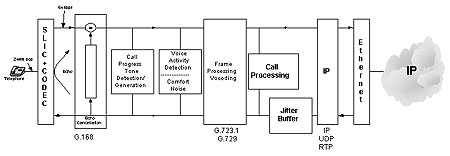
These delays are tabulated below in a typical example
Delay Budget for VoIP System (Example Only)
| Voice Activity Detection Delay | 2 to 10 msec |
| Packetization Delay | 1 to 30 msec |
| IP Network Delay | 100 to 200 msec |
| Depacketization Delay | 1 to 30 msec |
| Jitter Buffer Delay | 20 to 30 msec |
| Codec Delay | 1 to 30 msec |
| Total One Way Delay | 126 msec to 360 msec |
As can be seen from the above table, significant delays are possible in various parts of a voice packet system. Some of these delays are 'constant' and dependent on the type codec used within the system. The table below lists the typical delays for various codecs.
Typical Delays of Voice Codecs
| G.711 | 64 kbps | 125 usec |
| G.723.1 | 6.3 or 5.3 kbps | 30 msec |
| G.721 | 40 kbps and less | 125 usec |
| G.726 | 40 kbps and less | 125 usec |
| G.727 | 40 kbps and less | 125 usec |
| G.728 | 16 kbps | 2.5 msec |
| G.729a | 8 kbps | 10 to 15 msec |
| G.729e | 8 kbps | 10 to 15 msec |
Other delays in the VoIP system are 'variable' such as the IP Network Delay. This delay will be a function of the number of 'hops' in the packet network and other factors such as bandwidth, queuing, and retransmissions.
Similarly, circuit networks introduce delay and loss to speech traffic, but these are generally constant. A TDM switch introduces a constant delay as do multiplexing and other transmission equipment. End equipment may introduce delays associated with codecs and wireless transmission. In general, these delays will be constant per call.
Delay, loss, and echo are related in the following manner: Greater delay makes any echo more annoying; greater loss makes echo less annoying but quality is affected if levels are too low. Generally delay beyond 30ms requires echo cancellation.
With this introduction, we are now ready to measure delay and loss over circuit and packet networks. GL Communications makes T1 and E1 analyzers capable of transmitting calibrated test signals and measuring the same for delay and loss. One special application tailored for measuring echo, delay, and level is called the 'Delay/ERL' application. We describe its main features and provide examples of its use.
Introduction to the Delay/ERL Measurement Feature
One of the special applications provided with the PCI T1 and E1 Analyzers is the Delay/ERL application designed specifically to non-intrusively measure echo performance of circuit networks. This application can also be used to measure delay and loss over any circuit or packet network. The theory of operation is as follows: voice (pcm samples) in one direction is correlated to voice in the opposite direction. Delay and loss are derived from correlated calculations. To ensure accuracy, correlation is inhibited during double talk (minimum ERL setting). To measure delay and loss without regard to echo, this 'double talk' threshold can be effectively eliminated by setting the minimum ERL to 0 dB or -3 dB.
This application can be used to test intrusively as well as non-intrusively. In the non-intrusive mode, whatever signal is present in the system is used for the correlation. In the intrusive mode, a noise signal (or a signal from a file) is inserted and correlated with the returned signal.
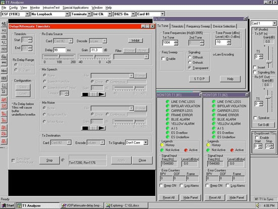
Some additional notes on operation of the Delay/ERL Application - please refer to the screen shot below
- Original Data and Returned Data - The two data streams that are correlated and compared for delay and loss. The user should properly identify these data streams, otherwise the analyzed data will not correlate properly.
- Delay and ERL - These measurements are based on correlation and comparison of the original and returned data streams. The data streams should be PCM format (A-law or u-law). If the 'original' and 'returned' data are reversed then erroneous measurements will be displayed.
- Delay Minimum and Delay Maximum - This establishes the window within which to correlate the original and returned data streams. Ensure that these values are reasonable for the system under test.
- ERL Minimum and Maximum - Set this to -3 dB and 60 respectively to eliminate the doubletalk detector from the correlation algorithm. During 'doubletalk', the correlation is not performed.
- Original Data Source - Three options are provided: T1 Input, Gaussian Noise, and File. T1 Input is used for non-intrusive measurements. In this case, the PCM data present on the lines and timeslots is used to perform the correlation. Of course, if idle PCM data is present, then valid correlations will not result and measurements may not make sense. For non-intrusive measurements, the two cards receivers should be set to 'Monitor' or 'Bridge' modes. Gaussian Noise and File are used for intrusive measurements. In these cases, a simulated noise signal or a signal provided in a file are used. In this configuration, the Analyzer card is either an endpoint or in a drop/insert configuration.
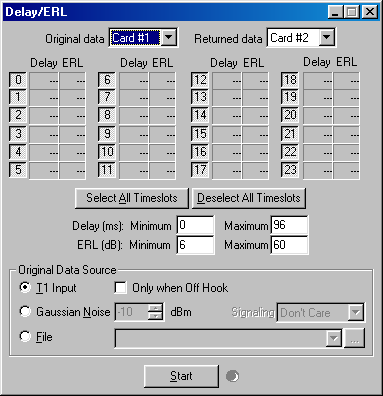
Screenshot of Delay/ERL Application Window
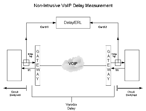
Diagram of Non-Intrusive VOIP Delay Measurement
Certain network configurations require that delay and loss (or gain) be measured non-intrusively i.e. without disruption of the channels in the system. Shown above is a test configuration that accomplishes this. Two Cards are necessary for the above measurement. Both cards should be set for Bridge or Monitor Modes.
The outputs and inputs of the circuit switched system are non-intrusively monitored by the Delay/ERL application. The signals at the right side are correlated and compared to the original signals on the left side. Computed delay and loss (gain) values are displayed in real-time for as many channels as appropriate.
In general, as long as traffic is present between the input and output Gateways, an accurate measurement of delay and loss is possible.
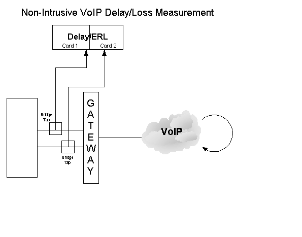
Diagram of Non-Intrusive VOIP Delay/Loss Measurement
Certain network configurations require that round-trip delay and loss (or gain) be measured non-intrusively i.e. without disruption of other channels in the system. Shown above is a test configuration that accomplishes this. Two Cards are necessary for the above measurement. Both cards should be set for Bridge or Monitor Modes.
The outputs and inputs of the circuit switched system are non-intrusively monitored by the Delay/ERL application. The signals originating from the system are correlated and compared to the signals terminating to the system. Computed delay and loss (gain) values are displayed in real-time for as many channels as appropriate.
In general, as long as traffic is present between the input and output Gateways, an accurate measurement of round trip delay and loss is possible.
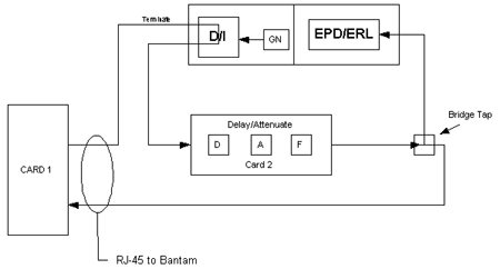
How to do a Non-Intrusive Delay/ERL Measurement Test Offline
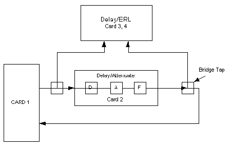
Use the configuration above to simulate and test Delay/ERL measurements for non-intrusive applications.
Card 1 represents a typical system sending data. In this case, set Card 1 to transmit noise on all but the last TS, using the Transmit Gaussian Noise Application.
The output of Card 1 is routed to Card 2 and through the Delay/Attenuate application and also non-intrusively to Card 3 for Delay/ERL purposes. Card 2 running the Delay/Attenuate software application simulates a path with (D) Delay, (A) Attenuation, and (F) Filtering. The output of Card 2 is routed back to Card 1 and also the signal is non-intrusively bridged to Card 4. At Card 4 the signal is correlated and compared to the original signal. Computed delay and loss (gain) values are displayed in real-time.
Configuration information for the Cards is given below:
- Card 1: Tx Gaussian Noise - Tx Noise on all TSs except for the last timeslot, Internal Clock, Terminate Mode
- Card 2: Recovered Clock, Terminate Mode, Run Delay/Attenuate software application
- Card 3: Bridge or Monitor Mode, Delay/ERL Application running
- Card 4: Recovered Clock, Bridge or Monitor Mode, Delay/ERL Application running with Delay/ERL measurement on Card 4
Shown below are the Analyzer set up screens for the offline simulation of non-intrusive Delay/ERL measurement.
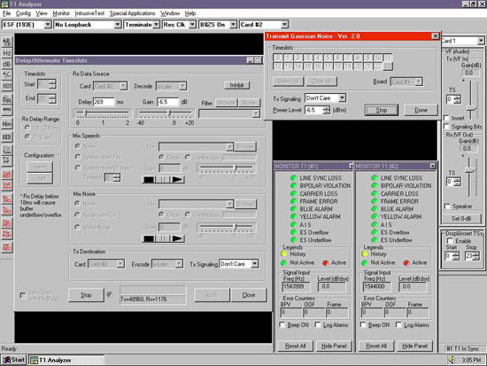
Screenshot of Delay/Attenuate Timeslots and Transmit Gaussian Noise
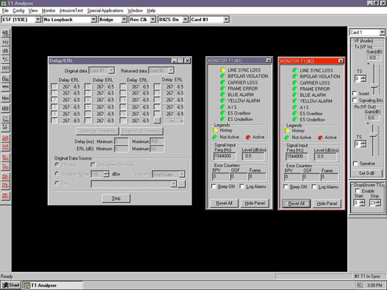
Screenshot of Delay/ERL With Monitors
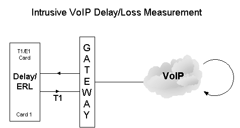
Intrusive VOIP Delay Measurement
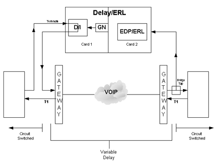
Certain network configurations require that delay and loss (or gain) be measured intrusively but without disruption of other channels in the system. Shown above is a test configuration that accomplishes this.
The output of the left system is routed through Card 1 in Drop/Insert Mode. Card 1 is set such that all data in all TSs is passed through except that in TS 1 Gaussian Noise is inserted. This noise is packetized by the Gateway and transported through the IP Network to the right hand Gateway, where it is depacketized and placed back into the same TS 1. At the right hand T1 Interface, the signal is non-intrusively bridged to Card 2. At Card 2 the signal is correlated and compared to the original signal. Computed delay and loss (gain) values are displayed in real-time.
The above can be performed on multiple TS as well by simply setting the D/I to multiple TSs. Measurement at the right hand side is performed automatically for as many timeslots as appropriate.
Configuration information for the Cards is given below:
- Card 1:
- Drop and Insert should be checked
- Delay/ERL Measurement application is invoked and set to transmit Gaussian Noise into Card 1 dropped timeslots
- Recovered Clock, Terminate Mode
- Card 2:
- Recovered Clock, Bridge Mode
Here is another possible network configuration to measure delay and loss (or gain) intrusively but without disruption of other channels in the system. Shown above is a test configuration that accomplishes this.
Only one Card is required for this test set-up. Card 1 is set to transmit Gaussian Noise (from within the Delay/ERL application) into all TSs. This noise is packetized by the Gateway and transported through the IP Network and looped back to the Gateway, where it is depacketized and placed back into the same TSs. At Card 1 the signal is correlated and compared to the original signal. Computed delay and loss (gain) values are displayed in real-time.
The above can be performed on multiple TS as well by simply setting the D/I to multiple TSs. Measurement at the right hand side is performed automatically for as many timeslots as appropriate.
Configuration information for the Cards is given below:
- Card 1:
- Delay/ERL Measurement application is invoked and set to transmit Gaussian Noise, all timeslots are activated
- Internal or Recovered Clock, Terminate Mode
How to test Intrusive Delay/ERL Measurement Offline
Use the configuration above to simulate and test Delay/ERL measurements for intrusive applications.
Card 1 represents a typical system sending data. In this case, set Card 1 to transmit tone on all but the last TS, using the Tx Tone application.
The output of Card 1 is routed through Card 3 in Drop/Insert Mode. Card 3 is set such that all data in all TSs is passed through except that in TS 1where Gaussian Noise is inserted. This noise is then routed through Card 2 running the Delay/Attenuate software application - simulating a path with (D) Delay, (A) Attenuation, and (F) Filtering. The output of Card 2 is routed back to Card 1 and also the signal is non-intrusively bridged to Card 4. At Card 4 the signal is correlated and compared to the original signal. Computed delay and loss (gain) values are displayed in real-time.
The above can be performed on multiple TS as well by simply setting the D/I to multiple TSs. Measurement is performed automatically for as many timeslots as appropriate.
Verify that tone is present on all TS, except the dropped/inserted TSs, where noise is being inserted and measured for Delay and ERL.
Configuration information for the Cards is given below:
- Card 1: Tx Tone application - Tx Tone on all TSs except for the last timeslot, Internal or Recovered Clock, Terminate Mode
- Card 2: Recovered Clock, Terminate Mode, Run Delay/Attenuate software application
- Card 3: Drop/Insert Mode checked, Recovered Clock, Terminate, Delay/ERL application running with Gaussian Noise inserted into some TSs
- Card 4: Recovered Clock, Bridge Mode, Delay/ERL application running with Delay/ERL measurement on Card 4
Shown below is the configuration for Card 1 and Card 2 for the offline simulation described above.
Screenshot of configuration for Card 1 and Card 2 for the offline simulation
Shown below is the configuration for Card 3 and Card 4 for the offline simulation described above.

Screenshot of configuration for Card 3 and Card 4 for the offline simulation
Resources
Note: PCs which include GL hardware/software require Intel or AMD processors for compliance.
 Back to Echo Canceller Testing Solutions Main Page