PacketExpert™ 1G Ethernet Tester
Portable (USB based) Quad Port Ethernet / VLAN / MPLS / IP / UDP tester with 4 Electrical Ethernet ports, 2 of the 4 ports can be Electrical or Optical ports, enabling testing on optical fiber links.
Request a Demo / Quote Brochure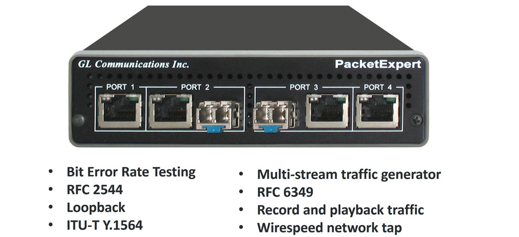
Overview
PacketExpert™ is a portable (USB based) Quad Port Ethernet / VLAN / MPLS / IP / UDP Tester with 4 Electrical Ethernet Ports (10/100/1000 Mbps) and 2 Optical Ports (100/1000 Mbps). Each GigE port provides independent Ethernet/VLAN/MPLS/IP/UDP testing at wire speed for applications such as BERT, RFC 2544, Loopback and ExpertSAM™. BERT is implemented for all layers (as depicted below). RFC 2544 is applicable for Layers 2, 2.5, and 3, and Loopback is applicable for Layers 2, 3, and 4. Further, PacketExpert™ also supports optional applications for advanced testing such as Record and Playback, PacketBroker, Multi Stream UDP/TCP Traffic Generator and Analyzer, and ExpertTCP™.
It truly takes confusion out of Ethernet / IP testing at all protocol layers - from Layer1 frames to IP/UDP packets. It can be used as a general purpose Ethernet to IP performance analysis tool for 10 Mbps, 100 Mbps and 1 Gbps Ethernet local area networks and wide area networks (WAN).
Two of the 4 ports in the PacketExpert™ unit support both electrical and optical interfaces per unit, enabling testing on optical fiber links as well. The electrical ports support 10/100/1000 Mbps, and optical ports support 100/1000 Mbps using SFP.
PacketExpert™ provides the following important functionalities –
- Wire speed BERT
- Smart Loopback
- RFC 2544 Testing
- Record and Playback
- ExpertSAM™
- PacketBroker
- Multi Stream UDP/TCP Traffic Generator and Analyzer
- ExpertTCP™ - (Available with Multi Stream Traffic Generator Analyzer)
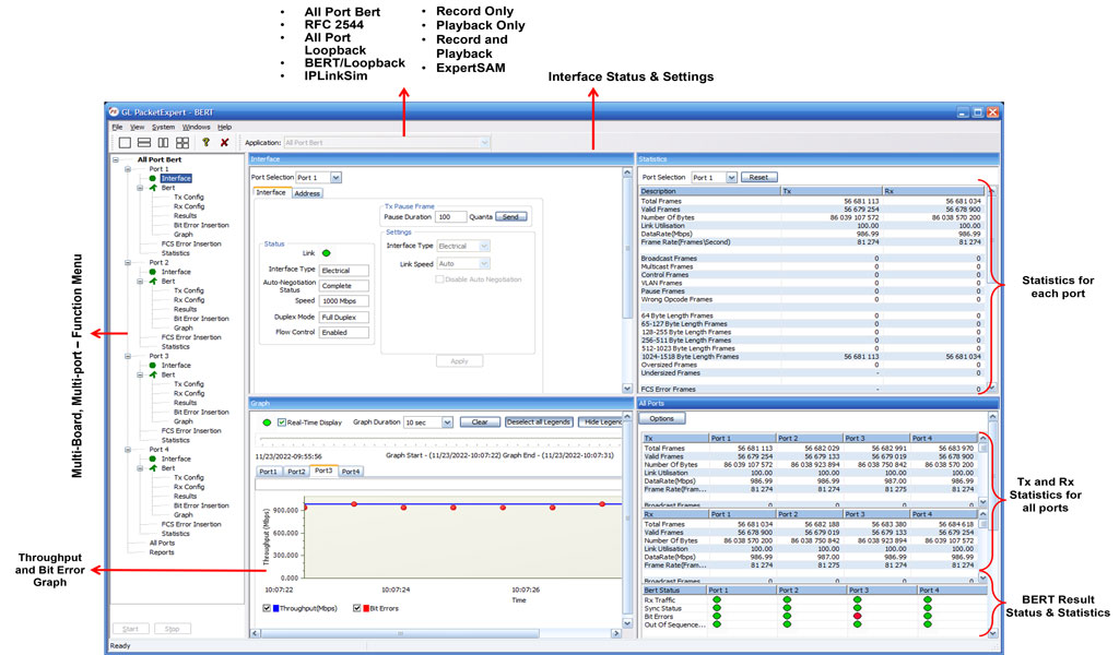
PackeExpert™ Main GUI
GL also offers other Ethernet/IP tester variants such as -
- PacketExpert™ 10GX (includes 4x 1G Electrical/Optical and 2x 10G optical interfaces) is available as portable stand-alone device and multiple such units can be stacked in rack-mount enclosure to form high density form factor solution
- HD-PacketExpert™ in Rack-mount enclosure - a higher density 12/24 GigE ports form factor solution
- Probe with PacketExpert™ 1G Multi-Port Ethernet- a hardware unit designed for easier portability and convenient for field testing
With additional licensing (CXE100) remote controlling of PacketExpert™ through multiple command-line based clients is available. The Command line Interface (CLI) feature allows the users to access all the aforementioned functionalities remotely via C#, Python clients and MAPS™ CLI Server.
Applications
- Multiport Ethernet Switch Testing
- Bit error-rate test (BERT) is for long-term service integrity testing
- Testing Multi-Protocol Label Switching (MPLS), Q-in-Q (Stacked VLAN) enabled Networks
- End to end testing of network paths, and network devices like Ethernet Switches/Router for QoS parameters
- In-depth troubleshooting of the Carrier network in the event of network failures or impairments
- SLA Benchmark Testing with RFC 2544 Tests
- Smart Loopback mode for single-ended testing scenarios
- QoS testing of Triple-play services to ensure that they fully qualify SLA parameters
- Terrestrial wireless, satellite, and other WAN technologies network validations
- Test VoIP network in real-time conditions to verify if it meets the quality requirements before you deploy
- Test routers, switches, VoIP handsets, VoIP PBXs, set-top boxes, and VoD servers
Main Features
Hardware |
|
Ethernet / IP Testing |
|
|
|
|
|
|
|
|
PacketExpert™ 1G - Portable
PacketExpert™ 1G Portable Unit
Interfaces |
|
Protocols |
|
Bus Interface |
|
Power |
|
Temperature |
|
Humidity |
|
Altitude |
|
Physical Specification |
|
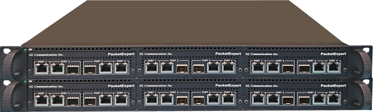
PacketExpert™ (1G) High-Density 12/24 GigE Ports (* Legacy Product)
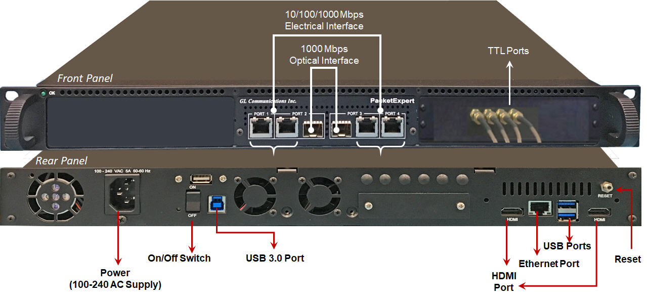
The sleek design of PacketExpert™ 1G portable hardware allows multiple such units to be easily placed in a 1U orStacked 1U rack mount enclosureto provide high density 12/24 GigE ports form factor solution for testing GigE switches, routers and network conditions. It is perfect ethernet test tool for customers who require multi-port testing but are constrained by lab space. A single PacketExpert™ rack-mount test solution with stacked rack units greatly reduces the licensing costs per device.
- PacketExpert™ 1U Rack-mount System is a 12-Port PacketExpert™ w/ Embedded Single Board Computer (SBC). SBC Specs: Intel Core i3 or optional i7 Equivalent, 240GB Hard drive, 8G Memory (Min), Windows® 10 64-bit Pro OS, USB 2.0 or 3.0 Ports, ATX Power Supply. 19" 1U Rackmount Enclosure (If options, then x 3).
- PacketExpert™ Stacked 1U Rack-mount System is a 24-Port PacketExpert™ w/Embedded Single Board Computer (SBC). SBC Specs: Intel Core i3 or optional i7 Equivalent, 240GB Hard drive, 8G Memory (Min), Windows® 11 64-bit OS, USB 2.0 or 3.0 Ports, ATX Power Supply. 19" 2U Rack-mount Enclosure (If options, then x 6).
 PacketExpert™ 1G Multi-Port Ethernet IP Tester Brochure

HD PacketExpert™ 1G 1U Rack-mount System (12 Port)
HD PacketExpert™ 1G Stacked 1U Rack-mount System (24 Ports) |
|
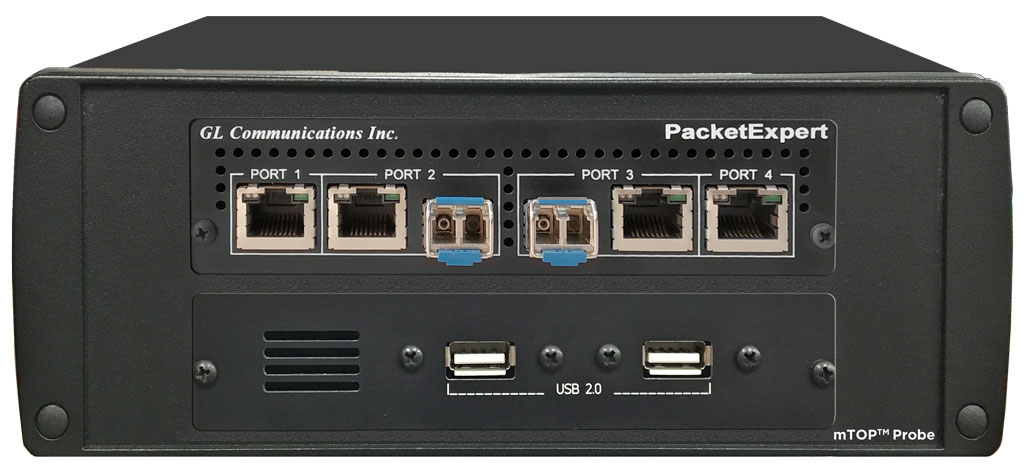
PacketExpert™ 1G Multi-Port Ethernet Probe
PacketExpert™ Probe is a portable Quad Port Ethernet/VLAN/MPLS/IP/UDP Tester with 4 Electrical Ethernet Ports (10/100/1000 Mbps) and 2 Optical Ports (100/1000 Mbps). Each GigE port provides independent Ethernet/VLAN/MPLS/IP/UDP testing at wire speed for applications such as BERT, RFC 2544, and Loopback. BERT is implemented for all layers. RFC 2544 is applicable for Layers 2, 2.5, and 3, and Loopback is applicable for Layers 2, 3, and 4. Further, PacketExpert™ also supports optional applications for advanced testing such as Record and Playback, ExpertSAM™, PacketBroker, Multi Stream UDP/TCP Traffic Generator and Analyzer, and ExpertTCP™.
It truly takes confusion out of Ethernet / IP testing at all protocol layers - from Layer1 frames to IP/UDP packets. It can be used as a general purpose Ethernet to IP performance analysis tool for 10 Mbps, 100 Mbps and 1 Gbps Ethernet local area networks and wide area networks (WAN).
Two of the 4 ports in the PacketExpert™ unit support both electrical and optical interfaces per unit, enabling testing on optical fiber links as well. The electrical ports support 10/100/1000 Mbps, and optical ports support 100/1000 Mbps using SFP. The embedded SBC makes it conveniently be used for field testing.
PacketExpert™ 1G Multi-Port Ethernet IP Tester Brochure
|
PacketExpert™ 1G Probe 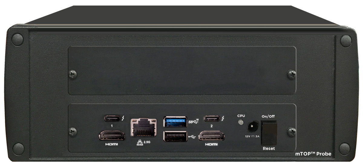
PacketExpert™ 1G Probe |
Refer to Packet /Ethernet Series Price Lists |
Supported SFP Modules
PacketExpert™ supports LC connectors and 850/1310/1550 nm SFP (Small Form-Factor Pluggable) modules. For users with different connector types, appropriate adapters such as LC-to-SC, LC-to-FC, or their reverse equivalents are required.
The following SFP modules are supported in 1G:
- 1000BaseLX - Long range, MM and SM
- 1000BaseSX - Short range, MM and SM
- 1000BaseT - Copper and many more

850/1310/1550 nm SFP Module

LC Connectors
Packet Analyzer
Measuring delay, jitter and packet loss through these networks is critical and network testers will need to precisely time events. Understanding the time from which the Air Traffic Controller keys PTT until the IP stream indicates that the PTT bit is set is a relevant testing scenario. This delay measurement is possible using GL’s Packet Analyzer - PacketExpert™. The Packet Analyzer is capable of generating event driven triggers based on certain packet filters. For each packet that satisfies filter criteria that will be forwarded for timestamping and synchronizing with other equipment.
Packet Analyzer hardware is capable of modifying the filtered packets using an inband method to convey information such as Timestamp (8 Bytes), Board Serial No. (1 Byte), Port No. (4 Bits), and Filter No. (2 bytes), to the output ports in the packet's MAC header.
PacketExpert™ 1U Rack-mount System |
4-Port PacketExpert™ w/ Embedded Single Board Computer (SBC). |
Interface: |
4 Total Ethernet ports |
Dimension: |
Length: 16 Inches |
Power Source: |
ATX Power Supply |
Connectivity: |
USB 2.0 and 3.0 Ports |
Layer 1 Frame Testing
In Layer1 testing, data is carried over Layer1 frames. Only the Preamble, SFD and Frame Check Sequence are present. Apart from these fields, the entire frame consists of the payload (BERT pattern).
GL’s PacketExpert™ supports Framed layer 1 testing with
- Intuitive GUI Layer selection option allows user to easily configure Layer1 testing, as well as other layers
- BERT and Loopback Testing
- Detailed Statistics
LAYER 1 Selection |
LAYER 1 Statistics |
Ethernet, Stacked Virtual LAN (VLAN) Testing Features
Ethernet is a most commonly used local area network (LAN) technology, whose transmission speed ranges from 10 Mbps to 10 Gbps. It is defined by 802.3 standards. A typical Ethernet frame structure is shown below:

Ethernet Frame
With the implementation of frame tagging, the Ethernet frames can be identified as belonging to a particular logical LAN. This allows different ports of a switch to be assigned to different logical LANs unlike traditional LANs. The 'tagging' feature evolved as VLANs allowing any user to be connected to any logical LAN, without having the requirements of physical presence in same premises. The VLANs simplifies security, manageability, and load sharing. The implementation is defined in 802.1q standard.
In order to accommodate tagging, a new optional IEEE 802.1Q tag field has been introduced between the Source MAC address and the Length field of the Ethernet frame as shown below:
Ethernet Frame with VLAN Tagging
A multi-tagged frame having multiple VLAN IDs, EtherTypes and other VLAN header bit fields constitute Q-in-Q frames, also referred to as VLAN stacking. This results in the tagged data frame to be tagged again with a VLAN tag, when it traverses the service provider network. The additional tag is removed at the edge of the service provider network before entering to destination network.
GL’s PacketExpert™ is capable of doing Wire speed Ethernet testing over Ethernet/IP networks.
GL’s PacketExpert™ Ethernet and Stacked VLAN testing supports -
- User configurable Source and Destination MAC Addresses (6 byte hex format), Len/Type field and VLAN fields. Length/Type field can be populated with User Defined value or preset values for IPv4/IPv6
- Up to 3 stacked VLANs configuration. The sequence of insertion is such that VLAN#1 forms the innermost tag; followed by VLAN#2 and VLAN#3 forms the outermost tag. Flexibility is provided to the user to select the VLAN type field (0x8100, 0x88A8, 0x9100, 0x9200, 0x9300) for each level
- BERT, RFC 2544, and Loopback Testing
- Setting the VLAN Type Field, VLAN Id, and the Priority Fields for each VLAN stack
- Statistics per stack position level
PacketExpert™ allows verifying the VLAN implementation meets the QoS expectations. User can set the VLAN Priority field to various levels and conduct the BERT and RFC 2544 tests to verify QoS. Utilizing the stacked VLAN feature, along with VLAN priority setting and combining with BERT/RFC 2544 testing helps extend the Layer 2 testing over carrier Ethernet networks.
VLAN Stack Field Type configured with Priority and VLAN IDs |
Stacked VLAN Statistics |
Multi-Protocol Label Switching (MPLS) Testing Features
Quality of Service (QoS) and traffic engineering are inherent features of MPLS. Testing essentially involves sending appropriately formatted MPLS packets through an MPLS provisioned network and verifying:
- Connectivity – traffic is properly routed to the correct destination, i.e., Label Switching Path
- Performance – Controlling QoS characteristics like Packet Loss, Latency, and Bandwidth within defined limits
Both end to end testing from customer edge to customer edge as well as testing within the core MPLS network is important. PacketExpert™ does both.
GL’s PacketExpert™ supports MPLS testing with MPLS related statistics like the Packet Counts per Stack position provided for detailed analysis.
GL’s PacketExpert™ MPLS testing supports
- Up to 3 MPLS stacked labels - Multiple MPLS label stacks are particularly useful in testing MPLS VPN implementations and multiple MPLS providers, and MPLS tunnels. MPLS#1 is the innermost label, while the other two are inserted in the outer levels
Multiple MPLS Label stack
- Configuring the Label value, the CoS bits (also known as the EXP or experimental bits) and the TTL (Time-to-Live) for each label, in addition to selecting the number of MPLS labels
- MPLS related statistics like the Packet Count per MPLS stack position are also provided for detailed analysis
- BERT and RFC 2544 test capabilities over MPLS Layer 2.5 – Supports sending MPLS enabled streams in its BERT and RFC 2544 tests and report various QoS characteristics like Bit Error Rate, Throughput, Frame Loss, and Latency
MPLS Label Stacking |
Stacked MPLS Statistics |
IP (Layer 3) Testing
Layer 3 configuration allows editing source and destination IP Addresses. In addition, users can configure various IP header fields like TOS, TTL, Protocol, Header Checksum, and Identification field. User can choose to allow hardware to calculate/verify checksum or provide a fixed value. IPv6 is also supported.
IPv4 and IPv6 configuration |
IP Statistics |
UDP (Layer 4) Testing
Layer 4 configuration requires source and destination UDP ports to be defined. User can choose to allow hardware to calculate/verify checksum or provide a fixed value.
UDP configuration |
UPD Statistics |
Error Insertion
PacketExpert™ provides 2 types of Error Insertion – Bit Error Insertion and FCS (Frame Check Sequence) Error Insertion. Bit Error insertion allows inserting Bit Errors into the outgoing Tx traffic. FCS Error insertion allows sending frames with wrong FCS value.
In both the Bit Error and FCS Error Insertion types, single as well as Rate Error Insertion is supported. Single error insertion allows user to manually introduce a single Bit/FCS error. Rate Error insertion allows the user to select a constant error rate, ranging from 10^-1 to 10^-9, to be introduced into the outgoing stream. Also, FCS Error insertion allows Continuous Error insertion, where every outgoing frame will have FCS error.
BERT Rx provides an option to process frames, even if they have FCS errors, as if they were normal BERT frames.
Bit Error Insertion |
FCS Error Insertion |
Wire Speed BERT
It can perform Wire speed BERT (Bit Error Rate Testing) on all ports simultaneously over Layer1, Framed Ethernet (Layer2), Stacked VLAN (Q-in-Q), Stacked MPLS (Layer 2.5), IP and UDP. It can generate and receive various BER patterns, including various PRBS patterns, to properly test the Ethernet to IP link. It analyzes the received BER traffic and provides various vital measurements.
With the capability to generate/receive traffic with stacked VLAN (Q-in-Q) and stacked MPLS, PacketExpert™ finds use in testing a wide range of networks – from testing individual links/switches, testing local Ethernet/IP networks (LAN), end to end testing of Wide Area Networks (WAN), testing Core/MPLS networks, and much more.
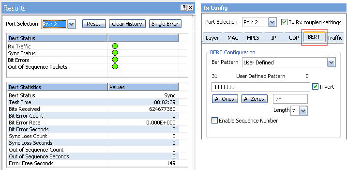
BER Testing
Loopback Testing
PacketExpert™ has all ports/2 ports Loopback capability. PacketExpert™ supports Layer-wise Loopback as well as Smart Loopback.
Loopback Types
- Smart Loopback - Analyses incoming traffic, automatically detects and swaps Source and Destination MAC, IP, and UDP addresses before sending back the packet
- Layer 1 – Loops back incoming packets as is
- Ethernet – Swaps Source and Destination MAC addresses before sending back the packet
- IP – Swaps Source and Destination MAC addresses, IP addresses before sending back the packet
- UDP - Swaps Source and Destination MAC addresses, Destination IP addresses, and UDP ports before sending back the packet
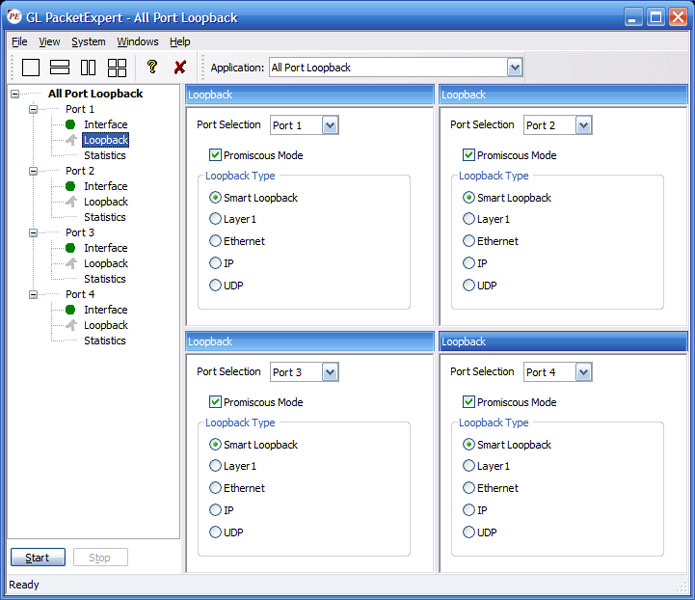
All Port Loopback Testing
RFC 2544 Testing, RFC 2544 (Single-port) Testing
PacketExpert™ supports Throughput, Latency, Frame Loss and Back to Back tests as specified in RFC 2544. Similar to BERT, RFC 2544 can be done over Framed Ethernet (Layer2), Stacked VLAN (Q-in-Q), Stacked MPLS, IP or UDP.
RFC 2544 allows the test frame to be configured with Stacked VLAN and Stacked MPLS. This way, end to end RFC 2544 test can be conducted across a Carrier Ethernet/MPLS network.
For Packet Expert™ 1G, at a time, RFC 2544 test can run either on Port #2 or Port #3 and it is not possible to run RFC 2544 test on both the ports (Port #2, Port #3) simultaneously.
For Packet Expert™ 10G or 10GX, at a time, RFC 2544 test can run either on Port #1 or Port #2 and it is not possible to run RFC 2544 test on both the ports (Port #1, Port #2) simultaneously.
RFC 2544 testing is supported on dual hardware interface as well as single port hardware interface.
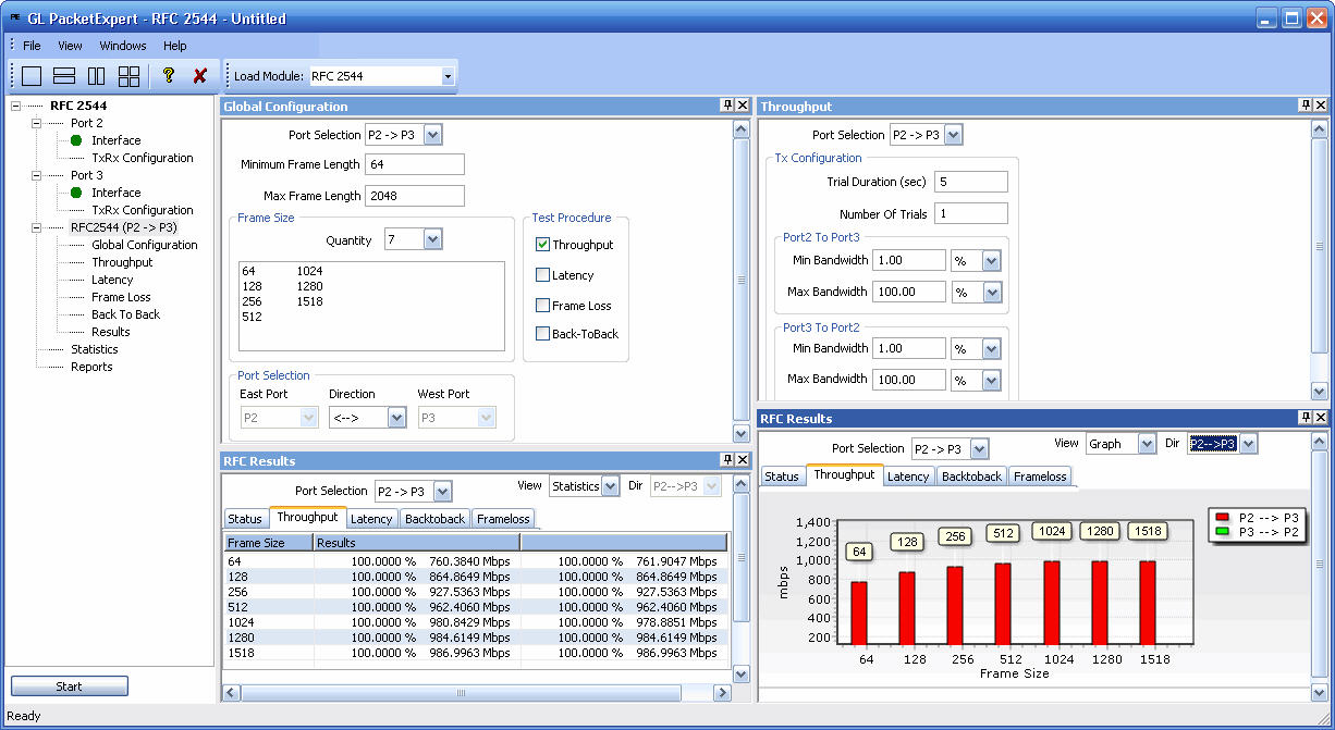
RFC 2544 Testing for Packet Expert™ 1G Dual Port
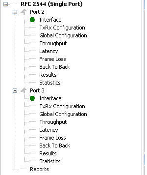
RFC 2544 Testing for Packet Expert™ 1G Single Port
Record Only and Playback Only
Record Only and Playback Only module is used to transmit and / or capture packets at wirespeed over network.
- Records the received packets into a file up to hard drive capacity (limited by disk write speed)
- Packet transmission from a file is limited to hard drive capacity
- Supported output file formats are *.pcap, *.ngcap, *.hdl, and *.dat
- DDR2 memory size of 2GB
- WireSpeed packet filter option to filter particular fields within protocol headers
- Results option displays some useful statistics and help to check the progress of the capture /transmission
- Playback can be done on up to 3 ports simultaneously or per port transmission
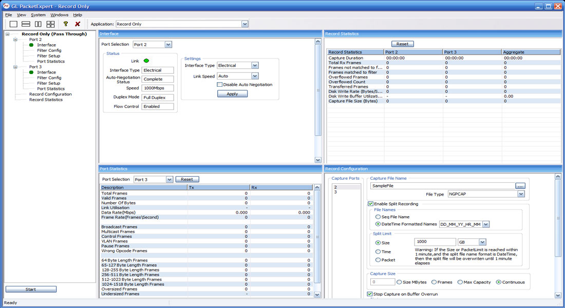
Record Only Mode
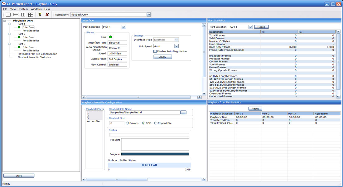
Playback Only Mode
ExpertSAM™
PacketExpert™ - ExpertSAM™ module is a single test conducted to validate service-level agreements (SLAs) as per ITU-T Y.1564 standard. ExpertSAM™ is intended for multiservice testing to measure the maximum performance of the DUT or the Network under test. In particular, it is aimed at solving the limitations of RFC 2544 test. ExpertSAM™ defines a methodology to test Ethernet-based services to carry a variety of traffic.
- Complete validation of Ethernet service-level agreements (SLAs) in a single test
- ITU-T Y.1564 standard compliance
- Supports multiple services with varying performance requirements that meets full load conditions
- Supports Single service (single stream) and multi services (multiple stream) testing
- CIR, CIR step rates, EIR, Traffic policing (Overshoot) service configuration test rates
- Frame Loss, Frame Delay and Frame Delay Variation measurement for guaranteed traffic
- Simultaneous validation of all the services quality over time
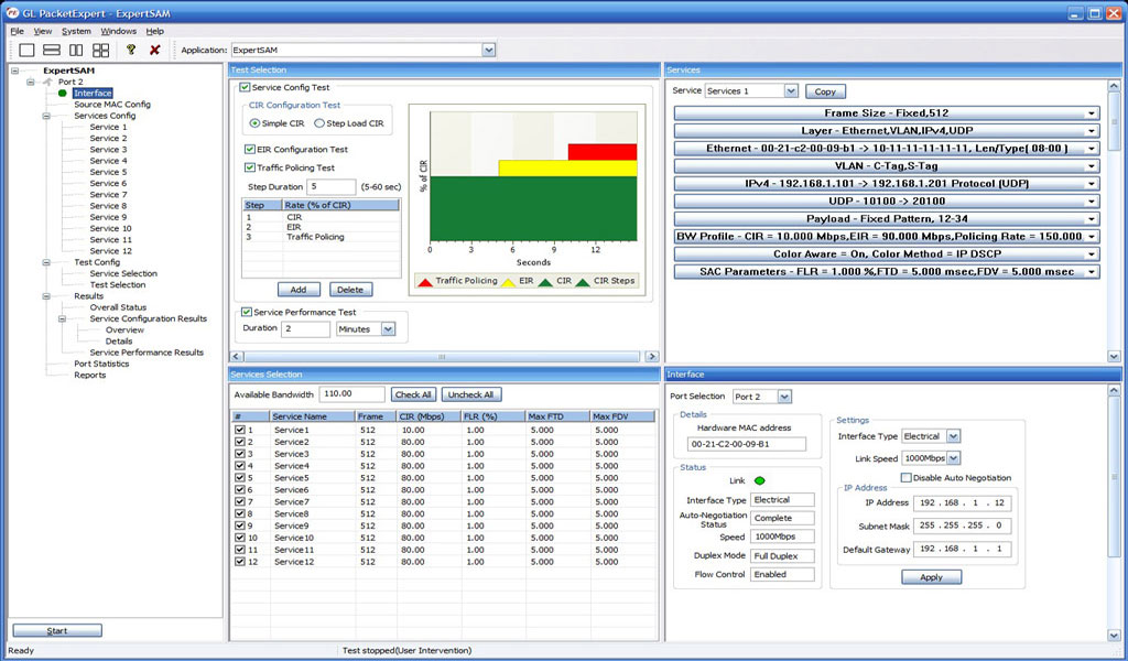
ExpertSAM™ Testing
PacketBroker™
PacketBroker is a new module added to GL’s PacketExpert™ that allows the test tool to be used as a highly precise non-intrusive Wirespeed Ethernet Tapwith all the necessary features such Pass through Tap, Hardware Filtering, Packet Modification and Output aggregation.
- Supports capturing on Port 2 and Port 3 PacketExpert™ that can be used in either SFP or Electrical mode
- Supports advance features like Filter, Aggregation, and Packet Modification
- Supports a total of 32 filters per PacketExpert™ unit, with 16 user-configurable filters per port
- Continuous mode (filters packets continuously) and Trigger mode (stops after the first packet is detected)
- Modify filtered packets to include useful information like timestamp with nanosecond precision, filter number, port number etc, an inband method of conveying the information to the packet analyser
- Aggregate filtered packets from pass-through ports and send out as a single stream on selected output port
- Supports forwarding the filtered, modified and/or aggregated packets on output ports (Port 1 or Port 4)
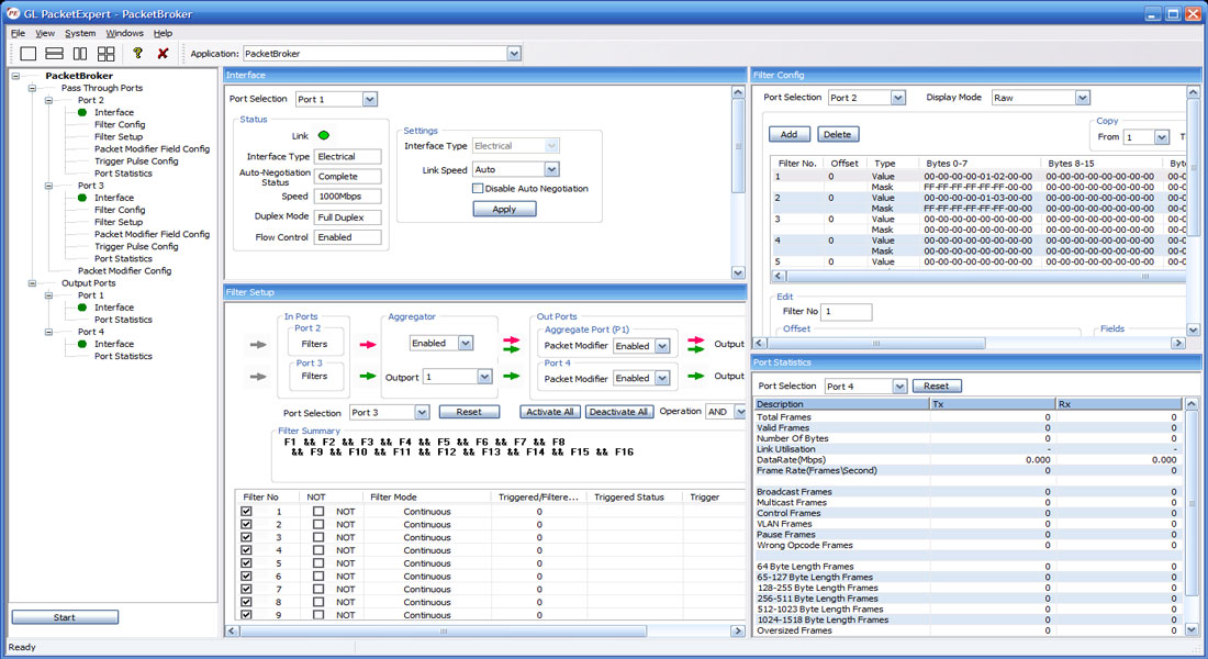
PacketBroker Testing
Multi-Stream UDP/TCP Traffic Generator and Analyzer
Multi-Stream UDP/TCP Traffic Generator and Analyzer (PXE108) is a hardware based Ethernet tester capable of generating multi-stream Ethernet traffic of varying packet length and also analyze the loopback traffic. This tool is available on GL’s powerful test platform – PacketExpert™ 1G, and finds itself useful for end-to-end testing of 1 Gbps WAN (Wide Area Network).
The application is also supported on PacketExpert™ 10G platform, where up to 16 multiple streams can be generated. But on PacketExpert™ 1G platform, up to 12 multiple streams can be generated.
The test results include Frame Loss, Frame Delay and Frame Delay Variation metrics for each stream. Easily monitor the bandwidth performance using live throughput consolidated graphical view for all the streams (up to 12 streams over 1G ports).
The Port#2 on PacketExpert™ 1G offers Smart Loopback functionality to loop the incoming traffic back to the source in the network. Loopback option helps in easy test setup, especially in end-to-end testing, when the other end is in a remote place. In such cases, one PacketExpert™ 1G can be put in constant Loopback at the remote end, and tests can be controlled at the local end.
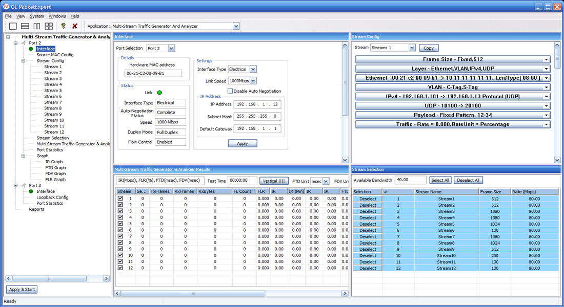
Multi-Stream Traffic Generations & Analysis on 1G (up to 12 Streams)
ExpertTCP™
ExpertTCP™ is an optional application with GL's PacketExpert 1G, a quad port tester for 1 Gbps Ethernet/IP Networks. It supports RFC 6349 based TCP Throughput test methodology.
GL's ExpertTCP™ performs bi-directional TCP throughput measurements in combination with another unit at the remote location (other end of the network), that acts as the TCP server. ExpertTCP™ supports both Upstream (Client → Server) and Downstream (Server → Client) direction testing.
ExpertTCP™ supports the TCP throughput testing as per RFC 6349 specification, conducted in 3 steps:
- Path MTU Discovery
- Determine Baseline RTT
- Conduct TCP Throughput test
Simultaneous bi-directional testing/unidirectional testing can be performed. Results are reported for both directions. The server at the remote location is completely controlled by the client side (located locally). User configures both client and server locally, and the results are displayed locally, avoiding the hassles of configuring the test at multiple locations.
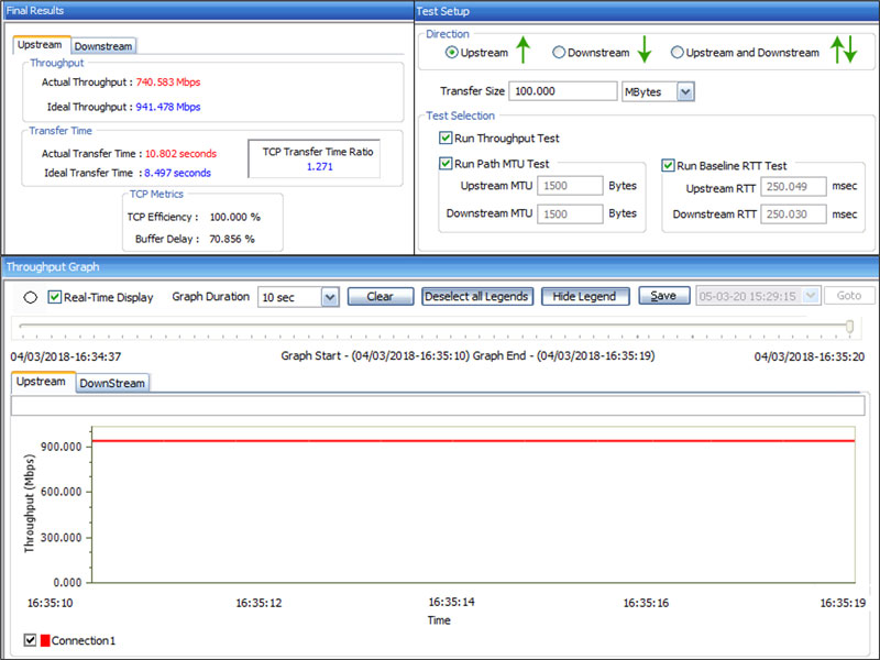
ExpertTCP™ on 1G (up to 8 TCP Connections)
Frame Statistics for BERT, RFC 2544, and Loopback Testing
Detailed statistics per port are provided. In addition to statistics like Frame Count, Frame Rate, Link Utilization (Layer 1 line rate in %), Data Rate (Layer 2 data rate in Mbps), etc., statistics are provided based on various categories like Frame Type (Broadcast, Multicast, VLAN), Frame Lengths (64, 65-127, 1024-1518, Oversized, Undersized), Protocol Type (IPv4, IPv6, UDP, TCP, ICMP, IGRP etc.)
Tx and Rx Frame Statistics
All Port BERT Statistics
Generate Report
The Report Generation option allows to create detailed test report in PDF and CSV formats.
Generate Report
Sample PDF Report
Command Line Interface (CLI)
With additional licensing, PacketExpert™ also supports Command line Interface (CLI) to access all the functionalities remotely using Python, C# clients and MAPS™ CLI Client/Server architecture.
PacketExpert™ can be configured as server-side application, to enable remote controlling through multiple command-line based clients. Supported clients include Python and C#. The PacketExpert™ APIs allows for programmatic and automated control over all PacketExpert™ platforms. Each MAPS™ CLI server can receive multiple client connections and offer independent execution to each client. Likewise, a single client can connect to multiple MAPS™ servers, including servers running different functions (BERT, Loopback, RFC 2544, Record Playback), permitting complex real-time test scenarios.
Client provides a simple scripting language, with programming facilities such as looping, procedures, and variables. The Client application includes a MapsClientIfc.dll file, a packaged library that enables communication with the Server from the client environment. The advantage of such communication enables user to control PacketExpert™ by sending commands and receiving responses in a scripting language already familiar with many users.
- Capability of remote operation, automation and multi-site connectivity using Python and C# clients and MAPS™ CLI server
- Scripts for MAC, VLAN, MPLS, IP and UDP layers testing
- Multiple PacketExpert™ can be controlled remotely from single client application via MAPS™ CLI server
- Scripts for Bert, Loopback, RFC 2544, Record Playback, PacketBroker, Multi Stream Traffic Generator and Analyzer, ExpertTCP™, IPNetSim, IPLinkSim, and ExpertSAM™ testing
The following depicts PacketExpert™ Python client interface used to perform basic BERT/BERT Loopback tests. Also, observe the executed commands in the MAPS CLI Server window after completing the test.
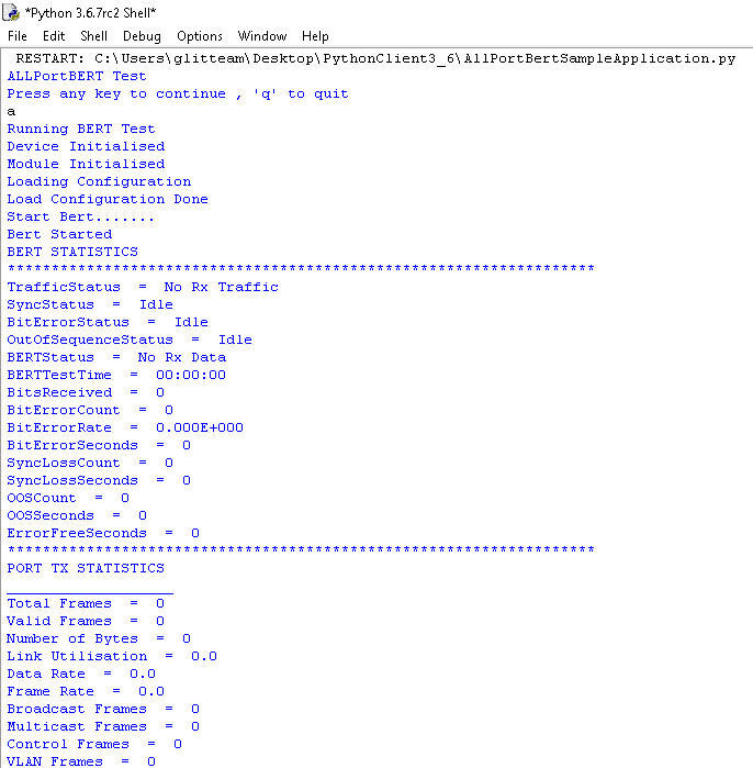
Command line based Python client
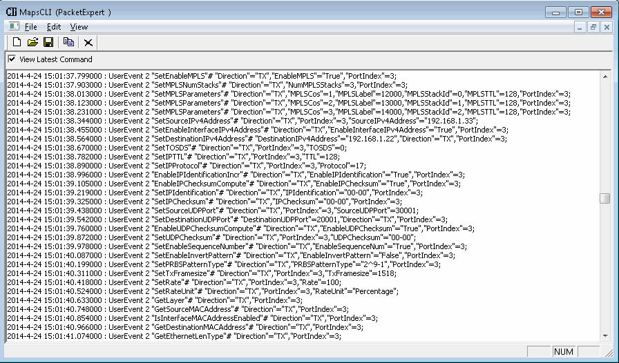
MAPS™ CLI Server for PacketExpert™
Buyer's Guide
Please Note: The 'Pxx' in the Item No. refers to the hardware platform on which the software will be running. Therefore, 'Pxx' can either be PXE (1G) or PXG (10G) or PXN (10GX) depending upon the hardware.
| Item | Description |
|---|---|
| PXE100 | PacketExpert™ 1G Accessories USB 2.0 cable (1) Power adapter 9 volts (1) Ethernet Cable (2) |
| CXE100 | CLI Server for PXE100 |
| PXE104G | PacketExpert™ - SA (4 ports) Rack-mount Accessories Rack-mount System with SBC (1) Power Supply as per the international standards (1) Ethernet Cable (3\6\12) |
| PXE112G | PacketExpert™ - SA (12 Ports) Rack-mount Accessories Rack-mount System with SBC (1) Power Supply as per the international standards (1) Ethernet Cable (3\6\12) |
| PXE124G | PacketExpert™ - SA (24 Ports) Rack-mount Accessories Rack-mount System with SBC (1) Power Supply as per the international standards (1) Ethernet Cable (3\6\12) |
| PXE105 | PacketExpert™ Wire speed Record /Playback for PXE100 |
| PXE107 | PacketBroker™ - for PXE100 |
| PXE108 | Multi-Stream UDP/TCP Traffic Generator and Analyzer - for PXE100 |
| Item | Related Hardware and software |
| PXN100 | PacketExpert™ 10GX Accessories USB 3.0 cable (1) Power adapter
|
| PXN101 | 10G option for PXN100 |
| CXN100 | CLI Server for PXN100 |
Quick Links
Webinar
WAN Impairment Simulation for Packet and TDM/Analog Networks
Wide Area Network Emulators IPNetSim™ 10G & 1G