T1 E1 J1 USB Controlled Switch
The T1 E1 J1 Switch can be used to control multiple T1 E1 lines to monitor, drop and insert, and perform intrusive and non-intrusive tests simultaneously.
Brochure Request a Quote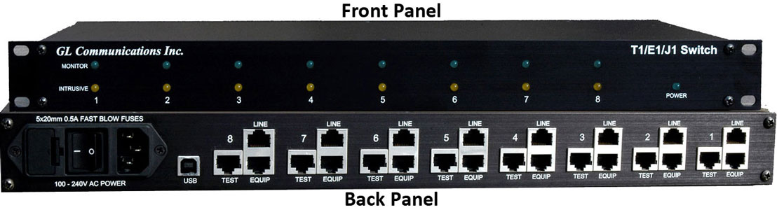
Overview
The T1 E1 J1 Switch can be used to control multiple T1 E1 lines to monitor, drop and insert, and perform intrusive and non-intrusive tests simultaneously. One can operate the switch in different modes by just changing relay settings remotely without requiring any changes to the physical connection. The T1 E1/J1 switch device is designed to monitor and intrusively test up to eight individual T1 E1/J1 lines.
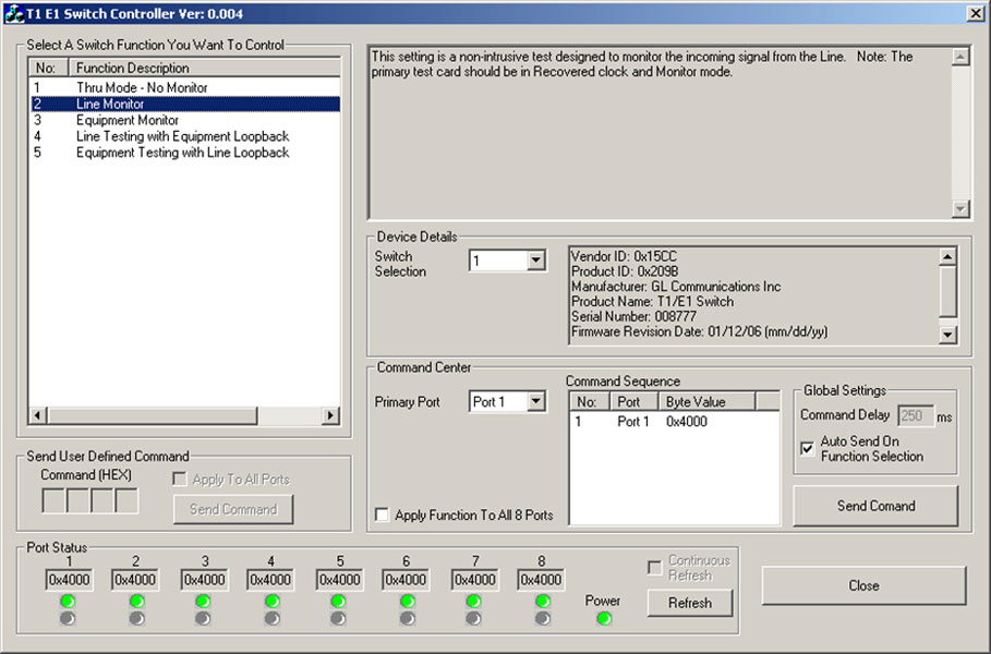
The switch can be remotely controlled via a USB connection. Both GUI as well as CLI control are available for controlling the switch in various modes for monitoring and diagnostic purposes.
The unit provides
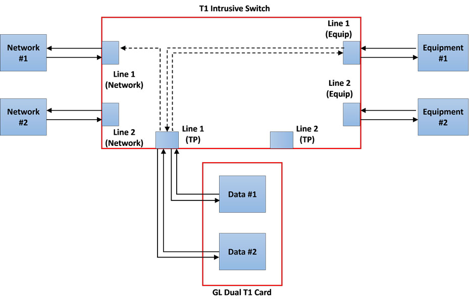
- Two RJ-48c connectors for a thru-mode connection for equipment and line connections
- One Rj-48c monitor connector for monitoring both directions of a full duplex high-speed line
- Up to 8 full duplex T1, E1, and J1 lines can be supported per unit
Main Features
- Monitoring & Intrusive testing can be done on both the equipment and line directions of a given T1 E1 J1 line
- The switch can be controlled locally or remotely for testing access to telecommunication lines
- Switch provides a fail-safe configuration on the event that power is lost
Working Modes of T1 E1 J1
The switch has three basic modes of operations:
- Through mode: This mode allows the signal to pass through the device by disconnecting the test access. With the test access disconnected, the test card from the line will be set inactive, and therefore the signals will pass through the switch without any monitoring
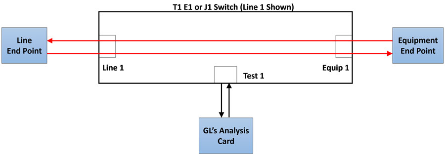
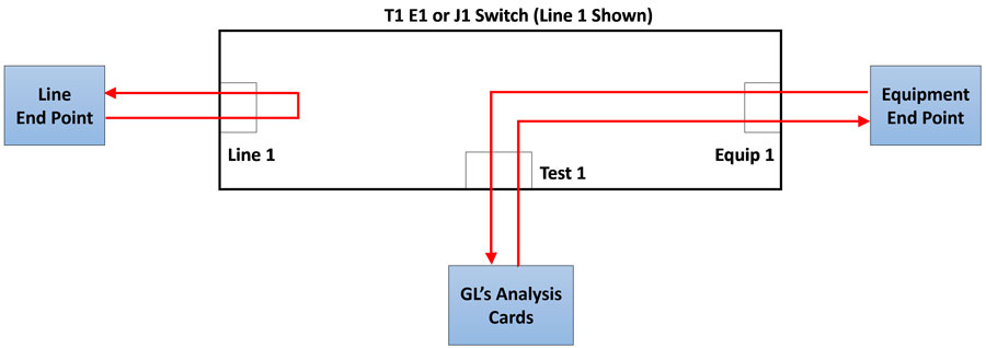
- Monitor-mode (Default State): In this mode user can monitor either line or equipment telecommunication sides
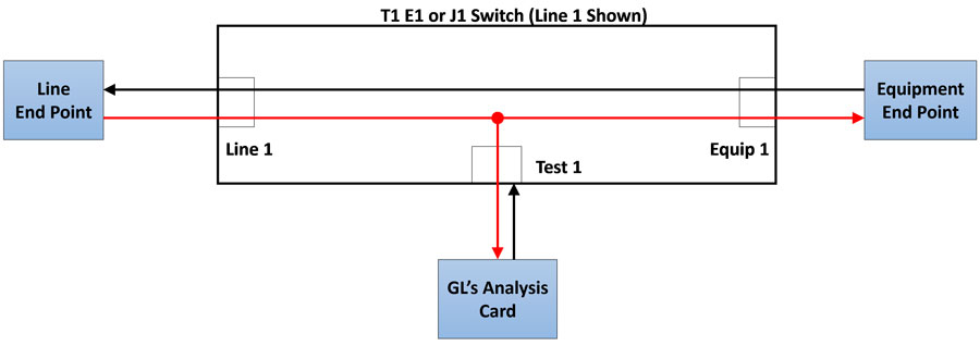
- Intrusive mode: This allows test access on either the line or equipment telecommunication sides
Other Detailed Configurations
The monitor and intrusive modes have additional detailed configurations, which allow greater control of the test access.
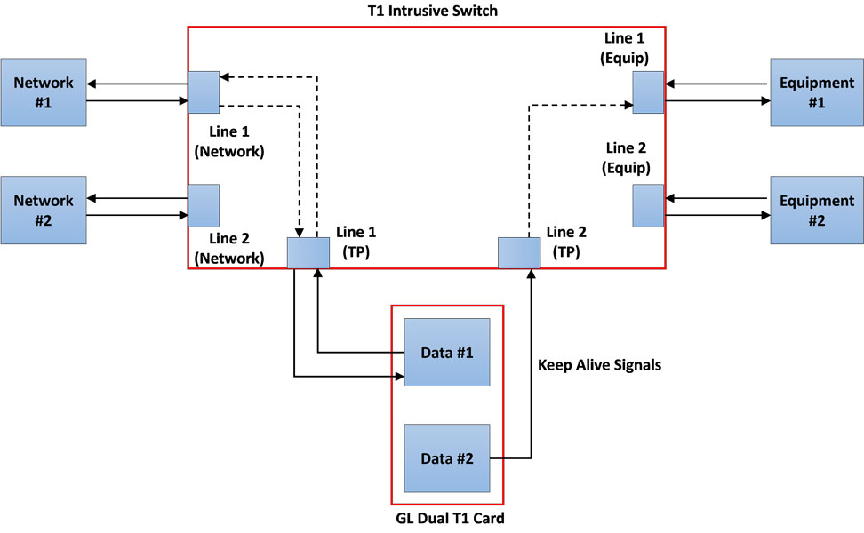
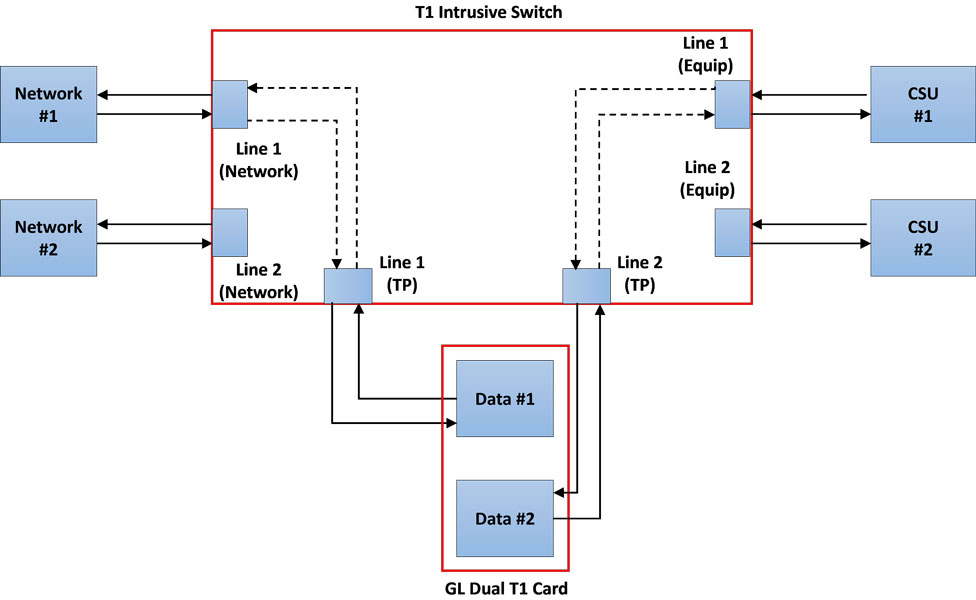
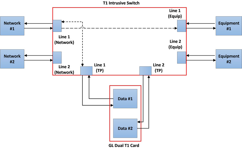
Line Testing with Keep Alive (Shared): This allows to test intrusively in the direction of Line. The secondary test cards provides Keep Alive signals indicating the line is active.
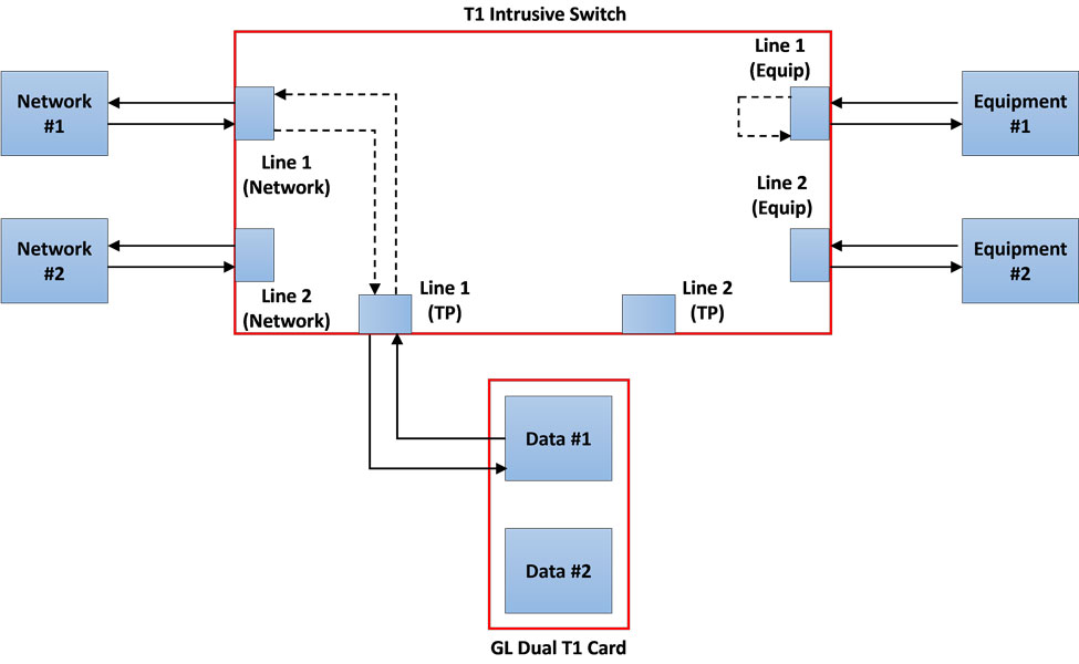
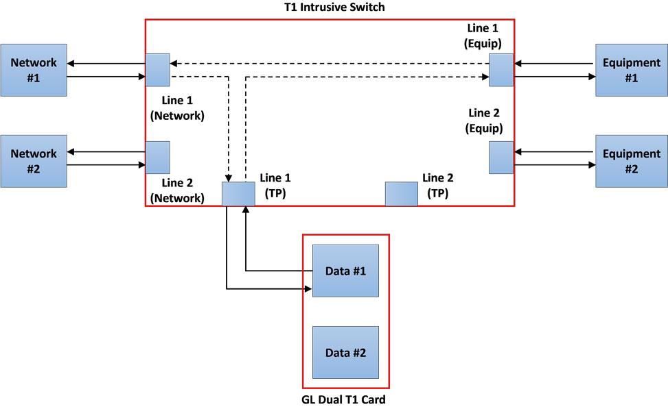
Line Testing with Equipment Loopback: This allows to test intrusively in the direction of Line. The Equipment side is looped back within the switch.
Dual Direction Monitoring: This allows to monitor the incoming signals from the Line and the Equipment non-intrusively.
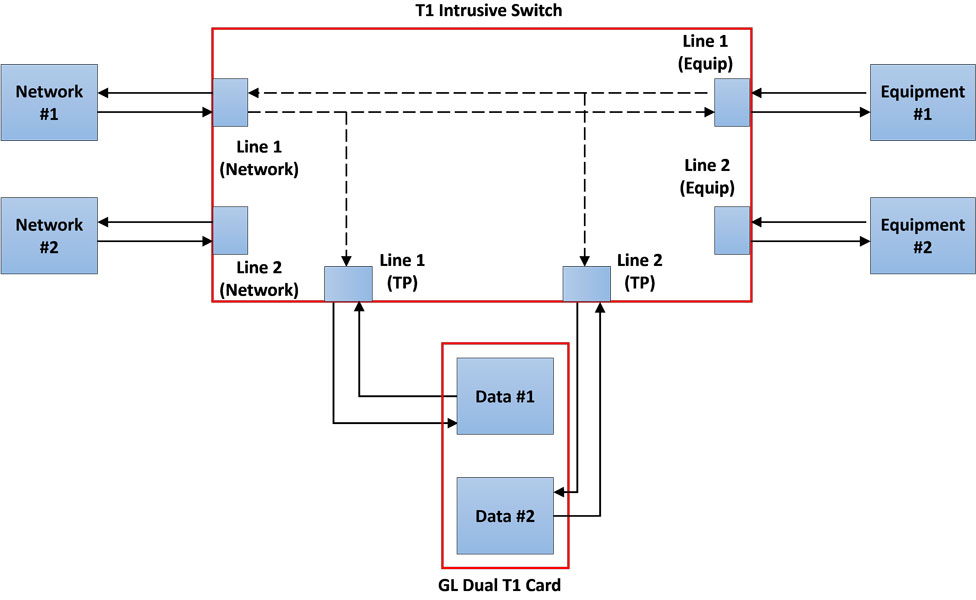
Dual Direction Testing: This allows to test the incoming signals intrusively from the Line and the Equipment at the same time.
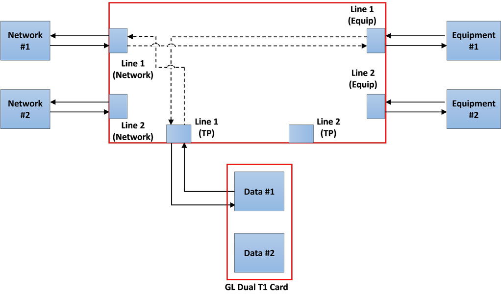
Monitor Line Loopback with Signal Thru: This allows to loopback the Line signal within the Switch and allow the test port to monitor. The signal from the Line is passed thru to the Equipment.
Drop & Insert to Equipment: It is an intrusive test allows to drop the received signal from the Line and insert the generated signal from the test card to the Equipment.
Drop & Insert to Line: It is an intrusive test allows to drop the received signal from the Equipment and insert the generated signal from the test card to the Line.
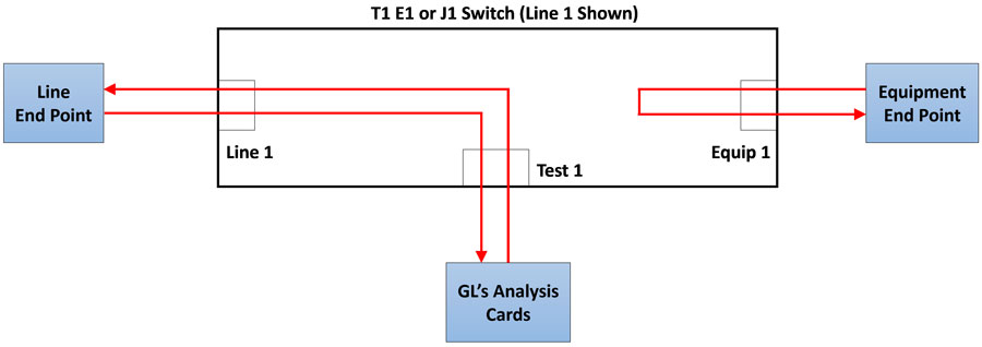
Dual Cable Connection: It is an intrusive test allows to test the Equipment/Line. The test card 2 provides Keep Alive signal towards the Line/Equipment respectively.
Software Controlling of Switch
The switch can be controlled using either T1 E1 Switch Application software or using GL’s Window Client Server (WCS). The T1 E1 J1 Switch can be operated in different modes by changing relay settings remotely without making any changes to the physical connection. This is quite useful in controlling multiple T1 E1 lines to monitor, drop and insert, and perform automated intrusive and nonintrusive tests simultaneously.
The Windows Client Server (WCS) is an application that allows the user to access the switch through a remote control script interface. The commands in the script interface is explained in the GL Server Command Reference manual.
Specifications
| Physical Dimensions Size Weight |
|
| Physical Interfaces | Front Panel |
| Software Requirements |
|
| Power |
|
Resources
Please Note: The XX in the Item No. refers to the hardware platform, listed at the bottom of the Buyer's Guide, which the software will be running on. Therefore, XX can either be ETA or EEA (Octal/Quad Boards), PTA or PEA (tProbe Units), XUT or XUE (Dual PCIe Express) depending upon the hardware.
| Item | Description |
| SWT001 | T1 E1 J1 Switch |
| Related Software | |
|---|---|
| XX610 | Transmit and Receive File Capability |
| Brochures | |
| T1 E1 J1 Switch - Brochure | |
| GL Product Lists | |
| Presentations |
| T1 E1 J1 Switch - Presentation |
Specifications are subject to change without notice.
 Back to Protocol Analysis Index Page