T3/E3 Alarms and Errors
Alarm and Error Generation
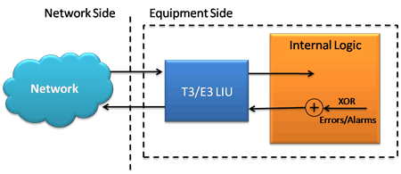
This application internally generates various errors and / or alarms and transmits them on the outgoing T3/E3 stream. The application can automatically insert errors at a specific error rate or insert single errors.

Logical Diagram for Alarm and Error Generation in T3 (DS3) /E3 Anlyzers
The alarm LEDs on the monitor window will indicate problems on the received signal through RED, YELLOW (history) or GREEN indications, allowing the users to do further investigation on the cause of the problem.
Generating Alarms
Generation of the following alarms is available.
LOS - Stops the T3/E3 transmission to create a Loss of Signal alarm condition.
LOF - (Loss of Frames) becomes active by checking the check box. By using the T3/E3 Configuration window, users can configure the type of LOF that is being generated.
AIS (Alarm Indication Signal) - this alarm is used to indicate a transmission failure within the network.
Idle - Idle alarm indicates that the line has not been provisioned for service and stays without triggering network alarms.
RAI/X-Bit - A receive (Rx) Remote Alarm Indication (RAI) alarm means that the far-end equipment has a problem with the signal received from the local equipment.
Generating Errors
Frame Error - This option inverts the outgoing F or M bit to create framing errors
P-Bit Error (T3 Only) - This option inverts the P-Bits to create P-Bit parity errors
C-Bit Error (T3 Only) - This option inverts the CP-Bits to create C-Bit parity errors in C-Bit Parity mode
FEBE Error (Far End Block Errors) (T3 Only) - This option sets the outgoing FEBE bits to 0, which indicates Far End Block Errors in C-Bit Parity mode.
BPV - BiPolar Violation (T3 Only) - Can only be inserted into a data stream that contains consecutive zeros. The AIS signal does not have consecutive zeros, so BPV errors cannot be inserted when the payload is set to AIS transmission.
Excessive 0's - Generates an EXcessive Zeros (EXZ) event. An EXZ occurrence is defined as three or more consecutive zeros in the T3 mode and four or more consecutive zeros in the E3 mode.
CV Errors (E3 Only) - A CV is defined in ITU O.161 as consecutive BPVs of the same polarity.
Error Rate
Single Error Insertion - These errors can be inserted one at a time by clicking on the insert button labeled as "1".
Continuous Error Insertion: Using this option users can automatically insert errors at a predefined error rate into the transmit stream.
User-defined Error Rate: Users can also insert errors continuously at a user defined error rate ranging between 10-2 and 10-9. Moving the track bar horizontally back and forth helps to set the error insertion rate or the required error rate to be inserted can be entered manually.
 Back to List of T3E3 Basic and Optional Applications Main Page

