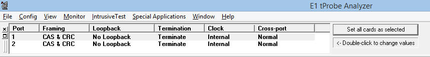
T1/E1 Interface Configuration
T1 E1 Line Interface application is included with T1 E1 Basic Software
Framing Formats for T1/E1 Systems
For E1 Systems
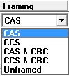
Channel Associated (CAS) or Common Channel Signaling (CCS) Framing Formats
GL's E1 Cards permit either Channel Associated Signaling or Common Channel Signaling modes. In CAS mode, timeslot 16 contains signaling bits for each channel. In CCS mode, timeslot 16 does not contain signaling information, it may contain user defined and formatted data.
Receive and Transmit Cyclic Redundancy Code (CRC)-4 Multiframe Formats
Two separate multiframe structures exist in CEPT environments: CRC-4 and Channel Associated Signaling (CAS). Both these multiframes use the frame structure but when used together they may not be aligned. The CRC4 multiframe is used primarily to assist in validating alignment at the FAS level but could also be used to monitor error performance.
Unframed Mode for E1
The application allows overwriting TS0 in E1 analyzers, so that user can use all the timeslots from 0-31, thus providing full 2.048-Mbps bandwidth.
Once the framing format is modified to Unframed E1, all applications are automatically set to work in this mode. This mode enables Tx on TS0 and disable auto resync on Rx
For T1 Systems
Currently two framing formats are supported: 193S and 193E as shown in the figure below. The 193S format is also referred to as the D4 framing format and the 193E format is also referred to as the ESF format.
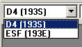
193S (D4) Framing Format
There are 12 frames per multiframe in the 193S format. Signaling information associated with each individual voice channel, such as on-hook/off-hook, call progress, and dial digits are transmitted within the voice channel in the LSB of each channel's codeword during the 6th and 12th frames. This technique, known as "robbed-bit" signaling, replaces the LSB of the PCM codeword with the signaling data. The signaling state in the 6th frame for each channel is known as the A bit. The signaling state in the 12th frame of each channel is known as the B bit. For voice grade applications, robbed-bit signaling does not noticeably degrade the signal quality.
193E (ESF) Framing Format
The 193E or Extended Superframe Format was developed to utilize the framing bit capacity for additional purposes. The number of frames per multiframe is expanded to 24 frames. This multiframe is also called a superframe. The 24 framing bit positions of each are divided into 3 channels. The FPS, or Framing Pattern Sequence, provides a synchronization signal for determining frame and superframe alignment. A 4kHz Facility Data Link (FDL) provides a dedicated channel for system messages. The Cyclic Redundancy Check (CRC) channel allows checksums to be transmitted with each superframe to monitor line quality.
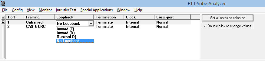
Loopbacks
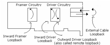
Three separate hardware loopbacks are provided on the T1/E1 Cards:
- Inward framer loopback (Inward Loopback (F))
- Inward driver loopback (Inward Loopback (D))
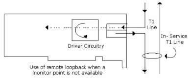
- Outward driver loopback (Outward Loopback (D))
- An additional software loopback called "Rx-to-Tx Loopback" is also provided. In software loopback, the received data is looped back to transmit data by the PC software
- Crossport Through (QUAD and OCTAL T1 E1 Analysis and Emulation Hardware, Universal T1/E1 Card and tProbe™ T1/E1 Analyzer only)
This mode is similar to the standard Outward Loopback except that the signal received on Card 1 (Port 1) is transmitted out onto Card 2 (Port 2). Likewise the signal received on Card 2 (Port 2) is transmitted out onto Card 1 (Port 1). The hardware is set to this mode (crossport through) by default whenever the board is powered up or down. This feature allows monitoring T1/E1 lines in-line while still being protected from loss of power to the board. This mode is effected entirely thru relays. This mode eliminates complex cabling.
Screen Shot of Invoking Crossport Through option
- Crossport Transmit (QUAD and OCTAL T1 E1 Analysis and Emulation Hardware, Universal T1/E1 Card and tProbe™ T1/E1 Analyzer only)
In this Mode, the data that would normally be transmitted on Card 1 (Port 1) is diverted and transmitted on Card 2 (Port 2) and the data that would normally be transmitted on Card 2 (Port 2) is diverted and transmitted on Card 1 (Port 1). The receive paths are completely unaffected. This mode is particularly useful for Drop and Insert and Error Injection applications in which the board analyzes and may insert traffic running between two pieces of T1/E1 equipment. This feature also eliminates complex cabling.
Screen Shot of Invoking Crossport Transmit option
Connection Options - Terminate, Bridge, and Monitor Modes
The T1/E1 input signal may be terminated using impedance, monitored, or bridged depending on user requirements.
Terminate
The incoming signal is electrically terminated in 100 ohms for T1 signals, 120 ohms for E1 signals.
This form of connection is normally used when connecting directly to a T1/E1 signal rather than monitoring a signal on an existing T1/E1 connection.
Bridge
The incoming signal is in series with a pair of 420-ohm resistors prior to termination with either 100
ohm (T1) or 120-ohm (E1) resistance. The pair wise 420-ohm resistance appears as a high impedance connection to the signal, and thereby
renders the "tap" non-intrusive. This form of connection is normally used to non-intrusively monitor transmissions on an existing T1/E1
connection. A "T" type of tap is required to simultaneously pass the signal to its intended destination and to provide a connection to the T1/E1 board.
Monitor
The incoming signal is assumed to originate from a monitor jack (which provides a tap and a pair
wise series resistance of 420 ohms). On the board the signal is terminated with either 100 ohm (T1) or 120ohm (E1) resistance. This form
of connection is normally used to non-intrusively monitor transmissions on an existing T1/E1 connection. A monitor signal is usually at a
level of-20dBsx that is 20 dB down from the nominal signal level measured at a DSX panel.
T1/E1 Clock Options
The T1/E1 analyzer has 3 clock options to choose. With internal clock option the transmit section is clocked using an internal oscillator. For recovered clock option , the transmit section is clocked using the clock derived from the received signal. If no received signal is present the internal clock is used. An external clock can be provided at the SMB input of the Cards or Dual USB Units. A TTL or CMOS level is acceptable. Apply a 1.544 MHz clock for T1 or a 2.048 MHz clock for E1.
Internal Clk:
The transmit section is clocked using an internal oscillator. 1 ppm is provided, when this
option is selected, the internal clock is also provided at the Ext Clk SMB connector.
Recovered Clk:
The transmit section is clocked using the clock derived from the received signal. If no
received signal is present the internal clock is used. When this option is selected, the recovered clock is also provided at the Ext Clk
SMB connector.
External Clk:
An external clock can be provided at the SMB input of the Cards or portable USB Units.
A TTL or CMOS level is acceptable. Apply a 1.544 MHz clock for T1 or a 2.048 MHz clock for E1. The Ext Clk at the SMB connector may
be an input or an output depending on the clock settings. For Internal and Recovered clock options, the SMB connector provides an
output clock. For External Clock option, the SMB connector provides for an externally provided input clock.
The interfaces to the T1/E1 Cards or portable USB units are balanced 120 ohm (E1) or balanced 100 ohm (T1) electrically. Systems employing 120-ohm interfaces can connect directly to the Cards or portable USB units. When connecting to systems employing 75-ohm interfaces, as is sometimes encountered in E1 systems, a 120-to-75 ohm transformer may be used. Contact GL Communications for these adapters. Connecting an unbalanced 75-ohm signal to a balanced 120-ohm interface (using a BNC to Bantam cable) will generally work for short distances.
Tx and Rx Configuration
Various options have been provided to configure the Tx/Rx parameters for all T1/E1 Cards.
For E1 Products
- Tx tab - Provides adjustable transmit clock frequency for testing frequency lock sensitivity of T1/E1 equipment (Universal HD cards and tProbe™ analyzer only), transmission of unframed all ones, signaling all ones, selection of output duty cycle, and option to select the bit type such as international, national, and extra bits on outgoing bit stream
- Rx Tab - Provides configuration options to detect the proper alignment of CAS multi-frames, automatically initiates frame search whenever CAS multi-frame alignment words are received in error, adjust receive signal level, auto and forced resync options to maintain the current framing position
- Tx & Rx Tab - Provides configuration options to define signaling Onhook/Offhook options by configuring ABCD signaling bits, receive and transmit data formats, transmit align frame positions, transmit remote alarm; loss of multi-frame alarm, enable or disable the jitter attenuation block from the 'transmit and receive' sides of the line interface.
For T1 Products
- Rx Tab – Provides configuration options to auto resync option to completely disable automatic resync, forced resync to force a receiver resync, apply resync on an out of frame (OOF) condition and /or on receive carrier loss (RCL) condition, out-of-frame criteria, resync algorithm to declare how many bits must be qualified in the framing pattern before the receiver declares the synchronization, Ft and Fs, network loop-back detection, and receive equalizer gain to adjust the receive signal for the receiver.
- Tx Tab – Provides options to enable or disable transmitting yellow alarm, transmitting blue alarm, line length selections from 0 to 655 feet (as measured from the transmitter to the DSX-1 cross connect), and Idle code selection.
- Tx_Rx Tab – Allows selection of B7 or transparent zero suppression, yellow alarm formats; auto detection of B8ZS / change-of-frame alignment, jitter attenuation, and jitter attenuation bandwidth; CRC-6 calculation (193E), and defining signaling onhook/offhook bits.
Screenshots
With Basic Software:
| For tProbe™, USB units |
|---|
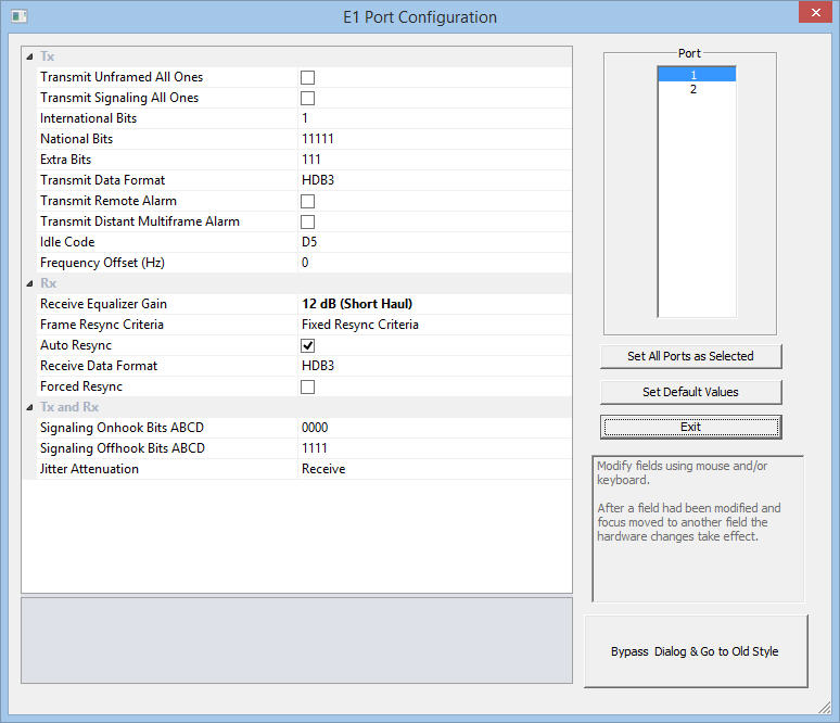 Tx Rx Configuration – E1 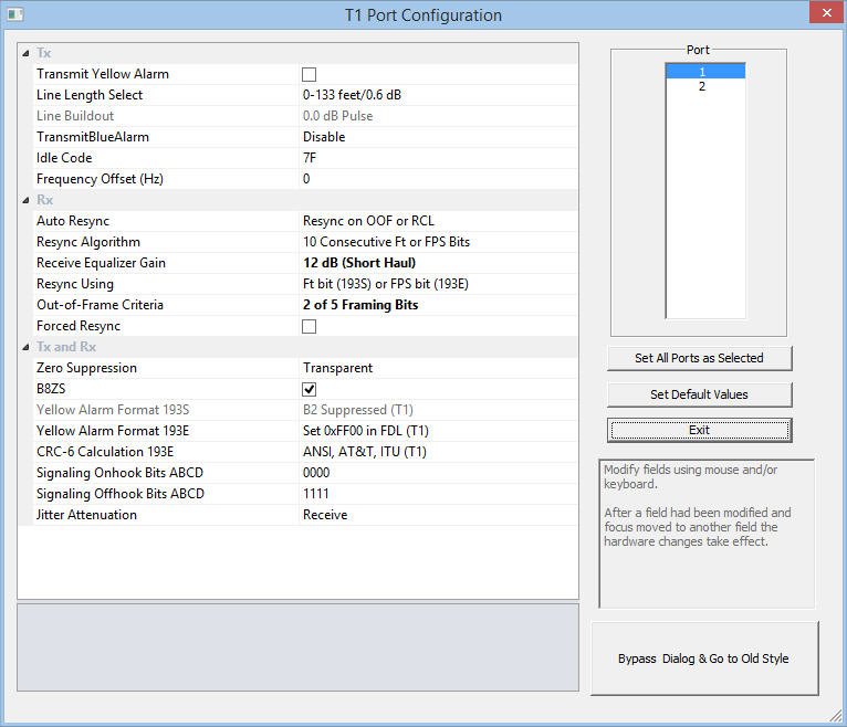 Tx Rx Configuration – T1 |
| For Universal, and Octal Cards |
|---|
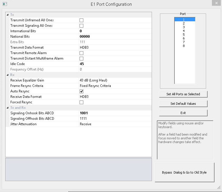 Tx Rx Configuration – E1 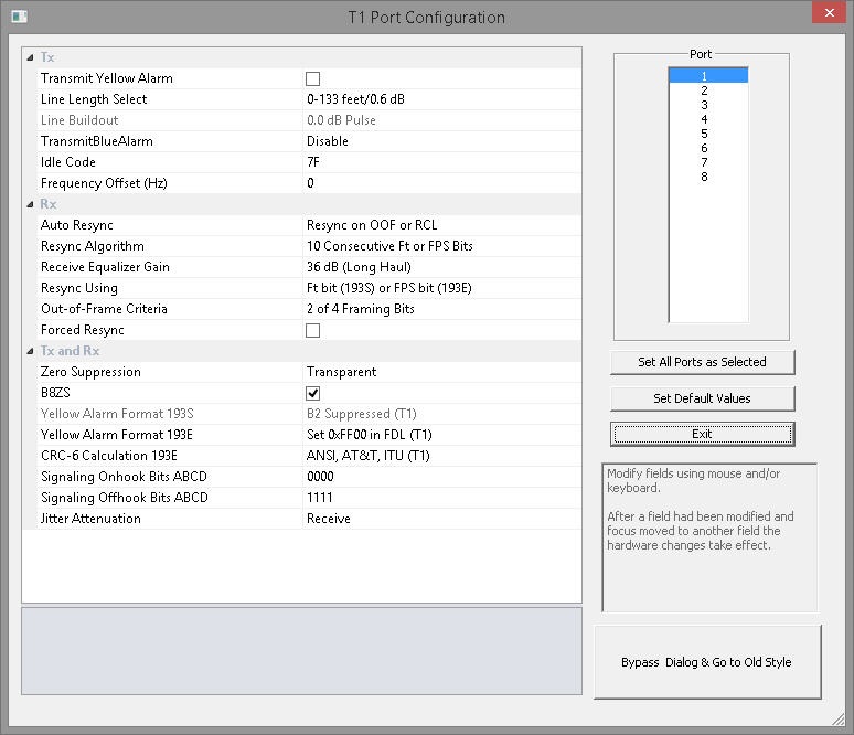 Tx Rx Configuration – T1 |
 Back to List of T1E1 Basic and Optional Applications Index Page