T1/E1 Frequently Asked Questions
How do I connect T1/E1 Card / Laptop Products?
In order to connect T1/E1 Card or Laptop products, the correct accessories are required.
- Recommended Accessories for T1/E1 ISA Card
- Recommended Accessories for T1/E1 PCI Card
- Recommended Accessories for Single T1/E1 Laptop
- Recommended Accessories for Dual T1/E1 Laptop
How to make physical connection to GL Products
- Figure 1: Series Connection
- Figure 2a: Series Connection using RJ-45
- Figure 2b: Series Connection using Bantam (ISA Cards)
- Figure 3: Monitor from a DSX-Patch Panel
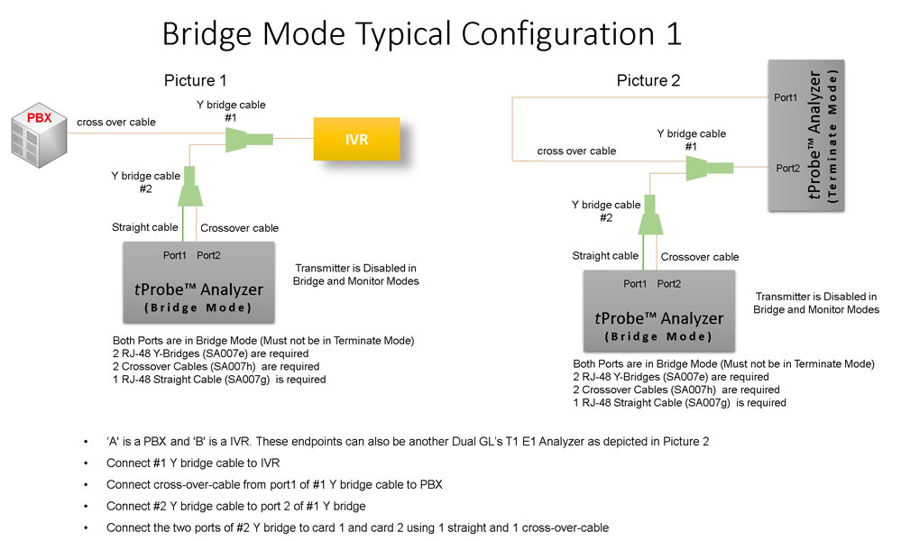
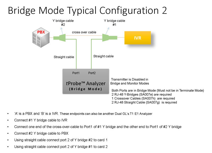
- Figure 4: Bridge Mode Connections for Monitoring T1/E1 Signals
for RJ-45
- Figure 5: Bridge Mode Connections Alternative Method
- Figure 6: Terminate Mode
- Figure 7. RJ-45 Connections
What accessories do I need with each product?
- Recommended Accessories for T1/E1 ISA Card
- Recommended Accessories for T1/E1 PCI Card
- Recommended Accessories for Single T1/E1 Laptop
- Recommended Accessories for Dual T1/E1 Laptop
What protocol analysis is supported?
The protocols supported include Voiceband, ISDN, SS7, MFC-R2, Frame Relay, Robbed Bit Signaling and many more. Refer to protocol analysis page.
How can I get better audio output from the T1/E1 Cards?
There is a Vf output that can be connected to any external speaker.
Is there any difference between the Ultra E1 (ISA Bus Card) and the PCI E1 (PCI Bus Card)?
The ISA Bus Cards have bantam jacks for the Digital and VF connections. The PCI Bus Cards have RJ45 (sometimes called RJ48C) jacks for the digital portion and miniheadphone jacks for the VF portion.
What PC platforms are available for the T1/E1 Cards?
The following PC Platforms are available for the Ultra T1/E1 Cards:
How do I view a captured file using CoolEdit Software?
Why can't I seem to get my Dual PCI GL card working with an Intel motherboard?
The Intel motherboard has multiple USB controllers. This causes a conflict with our Dual cards. For Windows 98, all that is needed is to go under device manager and disable the USB controllers. In NT 4, there should be no problem since USB is not used by the Operating System.
How do I measure the round trip delay of my system?
- Connect your system's input/output ports to the corresponding input/output ports of T1/E1 card.
- Put your system in loopback mode.
- Start precision delay measurement application which measures the exact delay present in your system.
What is the pin out of the connection in the analyzers?
Refer to the diagrams below. Our cards transmit on pins 4,5 and receive on pins 1,2. Pins 3 and 6 are not connected.
Pins 7 and 8 are shield.
Pin1- Receive Tip
Pin2 - Receive Ring
Pin3 - Not connected
Pin4 - Transmit Ring
Pin5 - Transmit Tip
Pin6 - Not connected
Pin7 - Shield
Pin8 - Shield
Straight Through Cable Pin-out

Cross Over Cable Pin-out
When connecting our cards together, use a crossover cable. When connecting to another system, determine on what pins the system is transmitting and receiving on, then use the appropriate cable.
How do I drop and insert when I have a RJ48 connection?
Use any of the following accessories to perform a drop and insert.
- Four Dual Bantam to RJ-48 cables (SA007d) and four Bantam Loopback Jacks (SA007m) - These accessories can be used to split the RJ48 connection as shown in the figure, or
- Use RJ 48 straights and crossovers with RJ-48 Splitter (SA007s). Use this gadget to eliminate the messy cabling in a. above. See diagram for an example
- See RJ-48 Splitter - Bridge Mode diagram
- See RJ-48 Splitter - Drop/Insert or Loopback Mode diagram
What is the difference in different loopback options?
Software Rx to Tx Loopback is used for testing purposes only. This application takes the data from the receive input and loops data at the PC memory for transmission to the transmit output side of the card.
The data from the PC is transmitted to a framer IC which frames the data into the appropriate T1 or E1 framing. The data from the framer is then sent to the line driver IC where the data is converted into a normal AMI, HDB3, or B8ZS signal to be transmitted out of the card.
- The inward loopback(F) loops the data at the framer back to the PC
- The inward loopback(D) loops the data at the driver back to the PC
- Outward Loopback is used when the monitor point is not available
Delay is more (1-2 secs) with the Tx/Rx Loopback when compared with driver/framer loopbacks (in the order of few ms). You may verify this using Precision Delay measurement application.
For more information, refer to T1/E1 Interface Configuration page.
When I use inward loopback (Framer or Driver) option why does the CARRIER LOSS indication remains RED?
The "Inward loopback (D/F)" is typically used to loopback the data of the transmitter. The term "transmit" refers to the data from the PC. The term "receive" refers to the data towards the PC.
The CARRIER LOSS indicates that the incoming data has more than 128 consecutive zeros. This typically occurs when there is no signal applied.
- When in "Inward loopback (D/F)" and no signal is applied to the receiver input, the CARRIER LOSS will illuminate (RED). The alarm can be ignored since the data that we are concerned with is being looped back from the transmitter
- When in "Inward loopback (D/F)" and a signal is applied to the receiver input, the CARRIER LOSS will illuminate (GREEN), indicating there is a valid input signal. Again, this can be ignored since this signal is not of interest
When the unit is in "No Loopback", the unit should function properly with the received incoming data.
When does a user use the different Crossport modes in tProbe/Universal cards?
No Crossport (Normal)
- Termination - Normal mode with terminate interface
- Bridging - There will be a momentary disruption while making connections, but once the Y cables are connected, connections are undisturbed
- Monitoring - This is the ideal situation, there won't be any disruption as the monitor jack already exists
Crossport Transmit
- Received data is not looped back, used for Drop and Insert
- Inline Error and Delay Insertion - Data is looped back using "Error Insertion" application, error can be inserted on to a timeslot/s and T1/E1 data is delayed inline
- Divert Transmit paths - data that is transmitted out of card1 goes out on card2 and vice versa, cards have to be in terminate mode to transmit
- Received paths are completely unaffected and monitored always ( Terminate, Bridge and Monitor interfaces)
We recommend selection of Terminate mode when CrossPort Transmit mode is selected.
Crossport Through
- Inline Monitoring - Data is passed thru seamlessly and monitored simultaneously
- Acts like Outward loopback on the different port. Signal received on port1 is transmitted out on thru port 2 and vice versa
- Irrespective of the interface setting (Terminate, Monitor, Bridge), data is passed thru
- This is the default setting when the unit losses Power or not connected to a PC
- Fail safe pass thru - Connection is not disrupted even if the PC looses power
We recommend selection of Bridge mode when CrossPort Through mode is selected.