GLC View - Waveform Viewing Application
Overview
GLC View is a waveform-viewing application. It has been designed specifically as a companion component for the GL Communications Inc. T1/E1 Echo Canceller Test Suite. The program may be used to view previously captured raw data files and their corresponding power.
Features
- Document/View Architecture. GLCView separates the data being viewed from its graphical presentation.
- Multiple Document Interface. The number of waveforms that can be simultaneously viewed is limited only by the resolution of the viewing screen.
- Synchronized raw data and windowed power graphs The power graph is automatically synchronized with the raw data graph. Thus when the raw data graph is scrolled, the power graph scrolls with it.
- Zoom-in and zoom-out capability The power graph is equipped with zoom-in zoom-out capability. Users may select a portion of the power graph with the mouse and zoom the selected portion to the entire graph area, thus allowing arbitrarily precise viewing.
- User-selectable power window length. The window in which the power is calculated is selectable by the user from 1 to 1000 ms.
Description
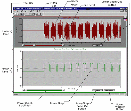
GLCView is a "Multiple Document Interface" (MDI) application. Its main window consists of an MDI frame, including a menu, toolbar, and standard system controls to maximize, minimize, resize, move, and close the window. It also contains the viewing area, in which the an indefinite number of files may be graphically displayed.
The display area of the view is divided into two panes. The upper pane is used to graphically display the raw data read from the file, which GLCView converts from compressed to linear form if necessary. For this reason, the top pane is referred to as the linear pane. GLCView uses the lower pane to display the power graph corresponding to the linear data in the upper pane, and is therefore referred to as the power pane.
Linear Pane: The linear pane is used to graphically display linear data in fivesecond segments. The pane contains a plot area in which the graph is displayed, horizontal(time) and vertical (linear value) axes, and controls that allow you to scroll through the data, and to size the graph to the plot area. When the graph is first displayed, GLCView analyzes the data in the first five seconds and uses the maximum and minimum values to scale the data to the plot area. While scrolling through the file, the character of the data may change in such a way that the initial scale is no longer appropriate. Linear pane's Zoom Out button helps to rescale.
Power Pane: The power pane is used to graphically display the power corresponding to the linear data in the upper pane. GLCView computes the power data by passing a sliding window over the linear data and computing the average power in that window. The pane contains a plot area in which the graph is displayed, horizontal(time) and vertical (linear value) axes, a scroll bar that allow you to scroll through the data, and buttons that allow you to zoom out and to bring up the Power Window dialog.
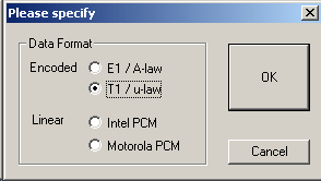
Data Format: In this dialog, the file format is selected. The user may select E1/A-Law format for E1 systems, or T1/m-Law for T1 systems. The user may also select 16-bit Intel ("Little-Endian" files or 16-bit Motorola ("Big-Endian") PCM files.
Power Calculation Window Dialog: GLCView computes the graph for the power pane in a variety of ways, as per the various tests in ITU-T G.168.
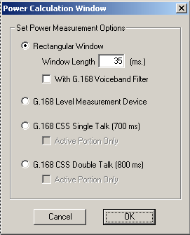
The various options are:
- G.168 Rectangular Window The power will be calculated by passing a sliding window over the linear data and computing the average power in that window. The sliding window is moved one point at a time over the linear data, so that each point in the linear data has a corresponding point in the power graph. The average power computed in the sliding window is assigned to the last point in the window.
- G.168 Level Measurement Device This device is essentially a frequency-weighed signal that has been squared to produce the power, and then passed through a 35 ms exponential filter. This device is specified for a number of tests, including Test 2, which deals with the convergence characteristics of the echo canceller.
- G.168 CSS Single-Talk This setting should be used to measure the average power of CSS single-talk files. The average power over a full cycle of CSS single-talk signal is calculated. The Active Portion Only check box is provided to calculate the power over the active portions of the signal.
- G.168 CSS Double-Talk This setting is used to measure the average power of CSS double-talk files. The average power over a full cycle of CSS double-talk signal is calculated. The Active Portion Only check box is provided to calculate the power over the active portions of the signal.
The window length can be set to any value from 1 millisecond up to 5 seconds. The value must be an integer. The default is 35 ms.
In conjunction with the power window, you may also provide the ITU-T G.168 Voice band Filter, which attenuates signal power outside the normal voice band of approximately 200 - 3500 Hz.
Vertical Scale Dialog
The Vertical Scale dialog is available for Linear PCM formats only. This button is not visible if encoded data format is chosen for viewing, as ITU-T G.168 has specific recommendations for computing the power of these signals.
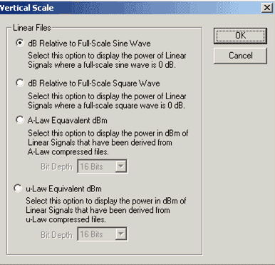
The following options are available:
- dB Relative to Full-Scale Sine Wave The point-by-point RMS power of the signal is calculated according to the method specified in the Power Calculation Dialog. The power is expressed relative to the power of a full-scale sine wave. The full-scale range is -32768 counts to 32767 counts.
- dB Relative to Full-Scale Square Wave The point-by-point RMS power of the signal is calculated according to the method specified in the Power Calculation Dialog. The power is expressed relative to the power of a full-scale square wave. The full-scale range is -32768 counts to 32767 counts. The values calculated by this method are 3.01 dB lower than those stated relative to a full-scale sine wave.
- A-Law Equivalent dBm This option is normally used for linear files that were originally derived from, or must be compared to, A-Law compressed files. The ITU-T G.168 A-Law formula is used to calculate the power. However, A-Law is a 13-bit format, whereas Linear PCM is a 16-bit format. Bit Depth specifies whether all 16 bits are being used, or whether 13-bit quantities are packaged in 16-bit numbers.
- µ-Law Equivalent dBm This option is normally used for linear files that were originally derived from, or must be compared to, µ-Law compressed files. The ITU-T G.168 µ-Law formula is used to calculate the power. However, µ-Law is a 14-bit format, whereas Linear PCM is a 16-bit format. Bit Depth specifies whether all 16 bits are being used, or whether 14-bit quantities are packaged in 16-bit numbers.
If bit depth specifies 13, it notifies the viewer that the signal is a 13-bit quantity. In other words, the signal values are exactly 13-bit A-Law expanded values packaged in a 16-bit format. The viewer can use the ITU-T G.168 A-Law power calculation formula directly for such signals.
If bit depth specifies 16, it notifies the viewer that the signal is a 16-bit quantity. The viewer must therefore downshift the sample values by 3 bits to use the ITU-T G.168 A-Law power calculation formula.
If bit depth specifies 14, it notifies the viewer that the signal is a 14-bit quantity. In other words, the signal values are exactly 14-bit µ-Law expanded values packaged in a 16-bit format. The viewer can use the ITU-T G.168 µ-Law power calculation formula directly for such signals.
If bit depth specifies 16, it notifies the viewer that the signal is a 16-bit quantity. The viewer must therefore downshift the sample values by 2 bits to use the ITU-T G.168 µ-Law power calculation formula.
Resources
Please Note: The XX in the Item No. refers to the hardware platform, listed at the bottom of the Buyer's Guide, which the software will be running on. Therefore, XX can either be ETA or EEA (Octal/Quad Boards), PTA or PEA (tProbe Units), XUT or XUE (Dual PCIe Express) depending upon the hardware.
| Item No. | Item Description |
|---|---|
| XX062 | Echo Path Delay/Loss Simulation Software |
| Related Software | |
| XX020 | Record and Playback of Files |
| XX051 | Synchronous Trunk Record Playback |
| XX051 | Synchronous Trunk Record Playback |
| XX022 | Dial DTMF/MF Digits Software (optional) |
| XX031 | Enhanced T1 / E1 Call Capture/Analysis Software (optional) |
| XX063 | Echo Path Delay/Loss Measurement Software |
| XX065 | G.168 Echo Canceller Test Suite |
| XX066 | Digital Echo Canceller |
| XX067 | Automated Echo Canceller Testing with or without VQT |
| XX068 | Semi-automated Scripted EC Testing |
| PKB100 | RTP Toolbox™ Application |
| Related Hardware | |
| FTE001 ETE001 |
QuadXpress T1E1 Main Board (Quad Port– requires additional licenses) OctalXpress T1E1 Main Board plus Daughter Board (Octal Port– requires additional licenses) |
| PTE001 | tProbe™ Dual T1 E1 Laptop Analyzer with Basic Analyzer Software |
| XTE001 |
Dual T1 E1 Express (PCIe) Boards (requires additional licenses) |